Category Archives: Microsoft Best Patterns & Practices

SharePoint Online: Software Boundaries, Limits and Planning Guide

This article describes some important limitations that you might need to know for different SharePoint Online plans in Office 365.
For example, it provides information about number of supported users, storage quotas, and file-size limits. This article covers a range of plans:
SharePoint Online in Office 365 Small Business and in Office 365 Enterprise, plus standalone plans.
The limits that are listed are for paid subscriptions. You might see different limits for trial plans andSharePoint Online preview sites. 

Note    In Office 365 plans, software boundaries and limits for SharePoint Online are managed separately from mailbox storage limits. Mailbox storage limits are set up and managed by using Exchange Online. For more information about how Exchange manages mailbox limits, see Mailbox types and storage limits for Recipients.

In this article

SharePointOnline2L-1[1]


SharePoint Online Feature availability

Need help determining which SharePoint solution best fits your organization’s needs?

The various Office 365 plans include different SharePoint Online offerings. These include:

  • SharePoint Online for Office 365 Small Business
  • SharePoint Online for Office 365 Midsize Business
  • SharePoint Online for Office 365 Enterprise, Education, and Government

You can choose the plan that best fits your organization’s needs. Each person who accesses the SharePoint Online service must be assigned to a subscription plan. SharePoint Online can be included in a Microsoft Office 365 plan, or it can be purchased as a standalone plan, such as SharePoint Enterprise Plan 1 or SharePoint Enterprise Plan 2.

Limits in SharePoint Online in Office 365 plans

In this section:

Limits for SharePoint Online for Office 365 Small Business

SharePoint Online Small Business and SharePoint Online Small Business Premium have common boundaries and limits. The following table describes those limits.

Feature Description
Storage per user (contributes to total storage base of tenant) 500 megabytes (MB) per subscribed user.
Site collection quota limit Up to 1 TB per site collection. (25 GB for a trial).

5,000 items in site libraries, including files and folders.

The minimum storage allocation per site collection is 100 MB.

Site collections (#) per tenant 1 site collection per tenant.
Subsites Up to 2,000 subsites per site collection
Total available tenant storage 10 GB + 500 MB per user.

For example, if you have 10 users, the base storage allocation is 15 GB (10 GB + 500 MB * 10 users).

You can purchase additional storage up to a maximum of 1TB.

Personal site storage 1 TB per user, as soon as provisioned.

This amount is counted separately, and does not add to or subtract from the overall storage allocation for a tenant. Personal site storage applies to a user’s OneDrive for Business library and personal newsfeed. For more information, see Additional information about OneDrive for Business limits.

Public Website storage default 5 GB

A SharePoint admin can allocate up to 1 TB (the limit for a site collection).

File upload limit 2 GB per file.
File attachment size limit 250 MB
Sync limits 20,000 items in the OneDrive for Business library, including files and folders.

5,000 items in site libraries, including files and folders.

Number of users 1 – 25 users
Number of external users invitees There is no limit to number of external users you can invite to your SharePoint Online site Collections. For more information, see Manage external sharing for your SharePoint Online environment

When reviewing the information on the previous table, remember that the base storage limits for Office 365 for Small Business (10 GB + 500 MB per subscribed user) will affect some of these values. For example, although SharePoint Online for Small Business imposes a limit of 1 TB per site collection, your particular tenant might not have enough storage available to contain a site collection of 1 TB.


 Important    It’s a good idea to monitor the Recycle Bin and empty it regularly. Content in the Recycle Bin is counted against the storage quota for a tenant. For example, if the Recycle Bin on a site contains 5 GB of content, that 5 GB is subtracted from the available storage.


Limits for SharePoint Online for Office 365 Midsize Business

The following table shows the software boundaries and limits for the SharePoint Online Midsize Business plan.

Feature Description
Storage per user (contributes to total storage base of tenant) 500 megabytes (MB) per subscribed user.
Storage base per tenant 10 GB + 500 MB per subscribed user.

For example, if you have 250 users, the base storage allocation is 135 GB (10 GB + 500 MB * 250 users).

You can purchase additional storage up to a maximum of 20 TB.

Additional storage at a cost per GB per month. To buy storage, see Change storage space for your subscription.

 Important    You can’t buy additional storage for a trial subscription.

Site collection quota limit Up to 1 TB per site collection. (25 GB for a trial).

5,000 items in site libraries, including files and folders.

SharePoint admins can set storage limits for site collections and sites. The minimum storage allocation per site collection is 100 MB.

Site collections (#) per tenant 20 site collections (other than personal sites).
Subsites Up to 2,000 subsites per site collection.
Personal site storage 1TB per user, as soon as provisioned.

Personal site storage applies to a user’s OneDrive for Business library and personal newsfeed. This amount is counted separately, and does not add to or subtract the overall storage allocation for a tenant. For more information about OneDrive for Business, see Additional information about OneDrive for Business limits later in this article.

Public Website storage default 5 GB

A SharePoint admin can allocate up to 1 TB (the limit for a site collection).

File upload limit 2 GB per file.
File attachment size limit 250 MB
Sync limits 20,000 items in the OneDrive for Business library, including files and folders.

5,000 items in site libraries, including files and folders.

Number of users 1 – 250 users
Number of external user invitees There is no limit to number of external users you can invite to your SharePoint Online site Collections. For more information see, Manage external sharing for your SharePoint Online environment

When reviewing the information on the previous table, remember that the base storage limits for Office 365 for Midsize Business (10 GB + 500 MB per subscribed user) will affect some of these values. For example, although SharePoint Online for Midsize Business imposes a limit of 1 TB per site collection and a limit of 20 site collections, your particular tenant might not have enough storage available to contain 20 site collections of 1 TB each.

 Important    It’s a good idea to monitor the Recycle Bin and empty it regularly. Content in the Recycle Bin is counted against the storage quota for a tenant. For example, if the Recycle Bin on a site contains 25 GB of content, that 25 GB is subtracted from the available storage.


Limits for SharePoint Online for Office 365 Enterprise, Education, and Government

One or more Office 365 subscriptions plans can be included as part of your subscription. This is true for the following plan offerings:

  • Microsoft Office 365 Enterprise subscriptions (E1 – E4)
  • Microsoft Office 365 Government subscriptions (G1 – G4)
  • Microsoft Office 365 Education subscriptions (A2 – A4)
  • Microsoft Office 365 Kiosk subscriptions (K1-K2)
  • SharePoint Online stand-alone subscription plans (Plan 1 and Plan 2).


These plans have common boundaries and limits. The following table describes those limits.


Feature Office 365 Enterprise plans (including E1 – E4, A2-A4, G1-G4, and SharePoint Online Plan 1 and Plan 2) Office 365 Kiosk plans (Enterprise and Government K1 – K2)
Storage per user (contributes to total storage base of tenant) 500 megabytes (MB) per subscribed user. Zero (0).

Licensed Kiosk Workers do not add to the tenant storage base.

Additional storage (per GB per month); no minimum purchase To buy storage, see Change storage space for your subscription.

 Important    You can’t buy additional storage for a trial subscription.

To buy storage, see Change storage space for your subscription.

 Important    You can’t buy additional storage for a trial subscription.

Storage base per tenant 10 GB + 500 MB per subscribed user + additional storage purchased.

For example, if you have 10,000 users, the base storage allocation is approximately 5 TB (10 GB + 500 MB * 10,000 users).

You can purchase an unlimited amount of additional storage.

 Important    If you have a Government Community Cloud plan, you can purchase additional storage up to 25 TB.

10 GB + additional storage purchased.

You can purchase an unlimited amount of additional storage.

 Important    If you have a Government Community Cloud plan, you can purchase additional storage up to 25 TB.

Site collection storage limit Up to 1 TB per site collection. (25 GB for trial).

SharePoint admins can set storage limits for site collections and sites. The minimum storage allocation per site collection is 100 MB.

5,000 items in site libraries, including files and folders.

 Important    If you have a Government Community Cloud plan, the limit is 100 GB.

Up to 1 TB per site collection. (25 GB for a trial). SharePoint admins can set storage limits for site collections and sites. The minimum storage allocation per site collection is 100 MB.

 Important    If you have a Government Community Cloud plan, the limit is 100 GB.

Kiosk workers (plans K1-K2) cannot administer SharePoint site collections. You will need a license for at least one Enterprise plan user to manage Kiosk site collections.

Site collections (#) per tenant 500,000 site collections (other than personal sites). 500,000 site collections.
Subsites Up to 2,000 subsites per site collection Up to 2,000 subsites per site collection
Personal site storage 1 TB per user (100 GB for government plans), as soon as provisioned.

Personal site storage applies to a user’s OneDrive for Business library and personal newsfeed. This amount is counted separately, and does not add to or subtract the overall storage allocation for a tenant.

For more information about OneDrive for Business, see Additional information about OneDrive for Business limits later in this article.

Not available.
Public Website storage default 5 GB

A SharePoint admin can allocate up to 1 TB (the limit for a site collection).

5 GB

A SharePoint admin can allocate up to 1 TB (the limit for a site collection).

Kiosk workers (plans K1-K2) cannot administer Sharepoint site collections. You will need a license for at least one Enterprise plan user to manage Kiosk site collections.

File upload limit 2 GB per file. 2 GB per file.
File attachment size limit 250 MB 250 MB
Sync limits 20,000 items in the OneDrive for Business library, including files and folders.

5,000 items in site libraries, including files and folders.

20,000 items in the OneDrive for Business library, including files and folders.

5,000 items in site libraries, including files and folders.

Maximum number of users per tenant 1 – 500,000+

 Note    If you have more than 500,000 users, please contact the Microsoft representative to discuss detailed requirements.

1 – 500,000+

 Note    If you have more than 500,000 users, please contact the Microsoft representative to discuss detailed requirements.

Number of external user invitees There is no limit to number of external users you can invite to your SharePoint Online site Collections. For more information, see Manage external sharing for your SharePoint Online environment There is no limit to number of external users you can invite to your SharePoint Online site Collections. For more information, see Manage external sharing for your SharePoint Online environment

When reviewing the information on the previous table, remember that the base storage limits for Office 365 for Enterprises (10 GB + 500 MB per subscribed user) will affect some of these values. For example, although SharePoint Online for Enterprise plans imposes a limit of 1 TB per site collection and a limit of 500,000 site collections, your particular tenant might not have enough storage available to contain 500,000 site collections of 1 TB each.

 Important    It’s a good idea to monitor the Recycle Bin and empty it regularly. Content in the Recycle Bin is counted against the storage quota for a tenant. For example, if the Recycle Bin on a site contains 25 GB of content, that 25 GB is subtracted from the available storage.


Limits for site elements in SharePoint Online

There are also limits for site elements of a SharePoint Online site. Here are some examples:

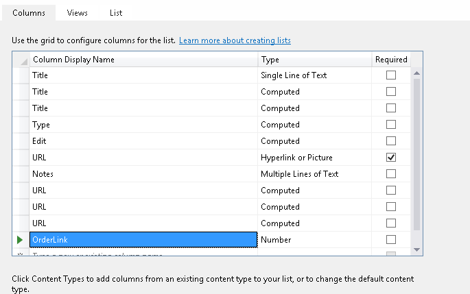
  • List and Library limits    Different types of columns have different limitations. For example, you can have up to 276 columns in a list for columns that contain a single line of text.
  • Page limits    You can add up to 25 Web Parts to a single wiki or web page.
  • Security limits    Different security features have different limits. For example, a single user can belong to no more than 5,000 security groups.


The specific elements for the previous site elements are too numerous to list here, but you can learn more about them in the TechNet article Software Boundaries and Limits for SharePoint 2013. In this linked article, only the sections on List and Library Limits, Page Limits, and Security Limits apply to SharePoint Onl


Additional information about OneDrive for Business limits

Each user in SharePoint Online for Office 365 gets an individual storage allocation of 1 TB for personal site content (100 GB for government plans). Personal sites include the user’s OneDrive for Business library, a Recycle Bin, and personal newsfeed information.

All SharePoint Online in Office 365 plans include the same storage allocation for individual personal sites. This storage allocation is separate from the tenant allocation.

For more information about how users can manage their individual OneDrive for Business allocation, see OneDrive for Business library limits.


Additional Resources


For information about this: Go here:
Office 365 connectivity limits To learn more about Internet bandwidth, port and protocol considerations for Office 365 plans, see Office 365 Ports and Protocols.
SharePoint feature availability To learn more about SharePoint feature availability and the SharePoint Online service in Office 365, see SharePoint Online Service Descriptions.
SharePoint Online search limits To learn more about the search limits for SharePoint Online, see Search limits for SharePoint Online.
Mobile devices To learn more about opening a SharePoint Online site from a mobile device, see Use a mobile device to work with SharePoint Online sites.
File types To learn about file types that you can’t add to a list, see Types of files that cannot be added to a list or library.
Online URLs To learn about SharePoint Online addresses, see SharePoint Online URLs and IP Addresses.
Site languages To learn how to set language for your sites, see Change your language and region settings.
Planning and deploying SharePoint Online
Change storage space

 Important    You can’t buy additional storage for a trial subscription.

How To : Use the Office 365 API Client Libraries (Javascript and .Net)

blog-office365

One of the cool things with today’s Office 365 API Tooling update is that you can now access the Office 365 APIs using libraries available for .NET and JavaScript.


\\8These libraries make it easier to interact with the REST APIs from the device or platform of your choice. And when I say platform of your choice, it really is! Office 365 API and the client libraries support the following project types in Visual Studio today:https://sharepointsamurai.wordpress.com/wp-admin/post.php?post=1625&action=edit&message=10

  1. NET Windows Store Apps
  2. .NET Windows Store Universal Apps
  3. Windows Forms Applications
  4. WPF Applications
  5. ASP.NET MVC Web Applications
  6. ASP.NET Web Forms Applications
  7. Xamarin Android and iOS Applications
  8. Multi-device Hybrid Apps

p.s: support for more projects coming on the way….

Few Things Before We Get Started

  • The authentication library is released as “alpha”.
    • If you don’t see something you want or if you think we missed addressing some scenarios/capabilities, let us know!
    • In this initial release of the authentication library, we focused on simplifying the getting started experience, especially for Office 365 services and not so much on the interoperability across other services (that support OAuth) but that’s something we can start looking for next updates to make it more generic.
  • The library is not meant to replace Active Directory Authentication Library (ADAL) but it is a wrapper over it (where it exists) which gives you a focused getting started experience.
    • However, If you want to opt out and go “DIY”, you still can.

Setting Up Authentication

The first step to accessing Office 365 APIs via the client library is to get authenticated with Office 365.

Once you configure the required Office 365 service and its permissions, the tool will add the required client libraries for authentication and the service into your project.

Lets quickly look at what authenticating your client looks like.

Getting Authenticated

Office 365 APIs use OAuth Common Consent Framework for authentication and authorization.

Below is the code to authenticate your .NET application:

Authenticator authenticator = new Authenticator();

AuthenticationInfo authInfo =
await authenticator.AuthenticateAsync(ExchangeResourceId);

Below is the JS code snippet used for authentication in Cordova projects:

var authContext = new O365Auth.Context();
authContext.getIdToken('https://outlook.office365.com/')
.then((function (token) {
    var client = new Exchange.Client('https://outlook.office365.com/ews/odata', 
                         token.getAccessTokenFn('https://outlook.office365.com'));
    client.me.calendar.events.getEvents().fetch()
        .then(function (events) {
            // get currentPage of events and logout
            var myevents = events.currentPage;
            authContext.logOut();
        }, function (reason) {
            // handle error
        });
}).bind(this), function (reason) {
    // handle error
});

Authenticator Class

The Authenticator class initializes the key stuff required for authentication:

1) Office 365 app client Id

2) Redirect URI

3) Authentication URI

You can find these settings in:

– For Web Applications – web.config

– For Windows Store Apps – App.xaml

– For Desktop Applications (Windows Forms & WPF) – AssemblyInfo.cs/.vb

– For Xamarin Applications – AssemblyInfo.cs

If you would like to provide these values at runtime and not from the config files, you can do so by using the alternate constructor:

image

To authenticate, you call the AuthenticateAsync method by passing the service’s resource Id:

AuthenticationInfo authInfo = await authenticator.AuthenticateAsync(ExchangeResourceId);

If you are using the discovery service, you can specify the capability instead of the resource Id:

AuthenticationInfo authInfo =
await authenticator.AuthenticateAsync("Mail", ServiceIdentifierKind.Capability);

The string to use for other services if you use discovery service: Calendar, Contacts and MyFiles

NOTE:

– For now, if you want to use the discovery service, you will also need to configure a SharePoint resource, either Sites or My Files. This is because the discovery service currently uses SharePoint resource Id.

– Active Directory Graph & Sites do not support discovery service yet

Depending on your client, the AuthenticateAsync will open the appropriate window for you to authenticate:

– For web applications, you will be redirected to login page to authenticate

– For Windows Store Apps, you will get dialog box to authenticate

– For desktop apps, you will get a dialog window to authenticate

image

AuthenticatorInfo Class

Once successfully authenticated, the method returns an AuthenticatorInfo object which helps you to get the required access token:

ExchangeClient client =
new ExchangeClient(new Uri(ExchangeServiceRoot), authInfo.GetAccessToken);

And also help you re-authenticate for a different resource when you create the service client.

AuthenticationInfo graphAuthInfo =
    await authInfo.ReauthenticateAsync("https://graph.windows.net/");

The library automatically handles token lifetime management by monitoring the expiration time of the access token and performing a refresh automatically.

Thats it! – Now you can make subsequent calls to the service to return the items you want!

Authentication Library

For .NET projects:

The library is available as a Nuget package. So, if you want to add it manually to your project without the tool, you could do so. However, you will have to manually register an app in the Azure Active Directory to authenticate against AAD.

Microsoft Office 365 Authentication Library for ASP.NET

Microsoft Office 365 Authentication Library for .NET (Android and iOS)

Microsoft Office 365 Authentication Library for ASP.NET

For Cordova projects:

You will need to use the Office 365 API tool which generates the aadgraph.js under the Scripts folder that handles authentication.

A Look At : Visual Studio Codelens

A Visual Studio Full of Panels

Let’s say you’re looking at a code file, specifically a method.  Your Visual Studio environment may look like this:

image

I’m looking at the second Create method (the one that takes a Customer).  If I want to know where this method may be referenced, I can “Find All References”, either by selecting it from the context menu, or using Shift + F12. Now I have this:

image

Great!  Now, if I decide to change this code, will it will work?  Will my tests still work?  In order for me to figure that out, I need open my Test Explorer window.

image

Which gives me a slightly more cluttered VS environment:

image

(Now I can see my tests, but I still need to try and identify which tests actually exercise my method.)

Another great point of context to have is knowing if I’m looking at the latest version of my code.  I’d hate to make changes to an out-of-date version and grant myself a merge condition.  So next I need to see the history of the file.

image

Cluttering my environment even more (because I don’t want to take my eyes of my code, I need to snap it somewhere else), I get this:

image

Okay, time out.

Yes, this looks pretty cluttered, but I can organize my panels better, right?  I can move some panels to a second monitor if I want, right?  Right on both counts.  By doing so, I can get a multi-faceted view of the code I’m looking at.  However, what if I start looking at another method, or another file?  The “context” of those other panels don’t follow what I’m doing.  Therefore, if I open the EmployeesController.cs file, my “views” are out of sync!

image

That’s not fun.

A Visual Studio Full of Context

So all of the above illustrates two main benefits of something like CodeLens.  CodeLens inserts easy, powerful, at-a-glance context for the code your looking at.  If it’s not turned on, do so in Options:

image

While you’re there, look at all the information it’s going to give you!

Once you’ve enabled CodeLens, let’s reset to the top of our scenario and see what we have:

image

Notice an “overlay” line of text above each method.  That’s CodeLens in action. Each piece of information is called a CodeLens Indicator, and provides specific contextual information about the code you’re looking at.  Let’s look more closely.

image

References

image

References shows you exactly that – references to this method of code.  Click on that indicator and you can see and do some terrific things:

image

It shows you the references to this method, where those references are, and even allows you to display those references on a Code Map:

image

Tests

image

As you can imagine, this shows you tests for this method.  This is extremely helpful in understanding the viability of a code change.  This indicator lets you view the tests for this method, interrogate them, as well as run them.

image

As an example, if I double-click the failing test, it will open the test for me.  In that file, CodeLens will inform me of the error:

image

Dramatic pause: This CodeLens indicator is tremendously valuable in a TDD (Test Driven Development). Imagine sitting your test file and code file side-by-side, turning on “Run Tests After Build”, and using the CodeLens indicator to get immediate feedback about your progress.

Authors

image

This indicator gives you very similar information as the next one, but list the authors of this method for at-a-glance context.  Note that the latest author is the one noted in the CodeLens overlay.  Clicking on this indicator provides several options, which I’ll explain in the next section.

image

Changes

image

The Changes indicator tells you information about the history of the file at it exists in TFS, specifically Changesets.  First, the overlay tells you how many recent changes there are to this method in the current working branch.  Second, if you click on the indicator you’ll see there are several valuable actions you can take right from that context:

image

What are we looking at?

  • Recent check-in history of the file, including Changeset ID, Branch, Changeset comments, Changeset author, and Date/time.
  • Status of my file compared to history (notice the blue “Local Version” tag telling me that my code is 1 version behind current).
  • Branch icons tell me where each change came from (current/parent/child/peer branch, farther branch, or merge from parent/child/unrelated (baseless)).

Right-clicking on a version of the file gives you additional options:

image

  • I can compare my working/local version against the selected version
  • I can open the full details of the Changeset
  • I can track the Changeset visually
  • I can get a specific version of the file
  • I can even email the author of that version of the file
  • (Not shown) If I’m using Lync, I can also collaborate with the author via IM, video, etc.

This is a heck of a lot easier way to understand the churn or velocity of this code.

Incoming Changes

image

The Incoming Changes indicator was added in 2013 Update 2, and gives you a heads up about changes occurring in other branches by other developers.  Clicking on it gives you information like:

image

Selecting the Changeset gives you the same options as the Authors and Changes indicators.

This indicator has a strong moral for anyone who’s ever been burned by having to merge a bunch of stuff as part of a forward or reverse integration exercise:  If you see an incoming change, check in first!

Work Items (Bugs, Work Items, Code Reviews)

image

I’m lumping these last indicators together because they are effectively filtered views of the same larger content: work items.  Each of these indicators give you information about work items linked to the code in TFS.

image

image

Knowing if/when there were code reviews performed, tasks or bugs linked, etc., provides fantastic insight about how the code came to be.  It answers the “how” and “why” of the code’s current incarnation.


A couple final notes:

  • The indicators are cached so they don’t put unnecessary load on your machine.  As such they are scheduled to refresh at specific intervals.  If you don’t want to wait, you can refresh the indicators yourself by right-clicking the indicators and choosing “Refresh CodeLens Team Indicators”

image

  • There is an additional CodeLens indicator in the Visual Studio Gallery – the Code Health Indicator. It gives method maintainability numbers so you can see how your changes are affecting the overall maintainability of your code.
  • You can dock the CodeLens indicators as well – just know that if they dock, they act like other panels and will be static.  This means you’ll have to refresh them manually (this probably applies most to the References indicator).
  • If you want to adjust the font colors and sizes (perhaps to save screen real estate), you can do so in Tools –> Options –> Fonts and Colors.  Choose “Show settings for” and set it to “CodeLens”.

How To : Design the Physical Architecture to Support Collaborative Development and ALM of SharePoint Foundation 2010 Application

Introduction

This article explains the physical architecture which fits best in collaborative development and ALM of SharePoint Foundation 2010 application and what are the servers and tools needed and how they play key roles in ALM of SharePoint Foundation 2010. The purpose of this article is to provide overall understanding of various servers and farms connected to each other in SharePoint Foundation.

Background

Basic understanding of different server OS & SharePoint Foundation 2010 is required.

Solution

Application Life-cycle Management (ALM) is the co-ordination of development life-cycle activities—including requirements, modeling, development, build, and testing. Recently, ALM has expanded beyond the application and the software development life cycle to also include business solution governance, infrastructure management, operations, and support.

You can use ALM to help align your organization in the context of a software solution in business, development, and operations. With an application development platform that supports ALM, you can provide integration between the various tools used and activities performed within each of these capabilities.

There are main four types of staging servers with standalone developer’s environment which plays a key role in ALM of SharePoint 2010 application:

  1. Development SharePoint Farm
  2. Team foundation server
  3. Integration/Testing Farm
  4. Production Farm
    +
    Developer’s Workstation

The below figure is a physical architecture which depicts how each sever is interconnected to support collaborative development and ALM for SharePoint Foundation 2010 application:

Click to enlarge image

Development SharePoint Farm

A SharePoint farm is fundamentally a collection of SharePoint role servers that provide for the base infrastructure required to house SharePoint sites. The farm level is the highest level of SharePoint architecture, providing a distinct operational boundary for a SharePoint environment. Each farm in an environment is a self-encompassing unit made up of one or more servers, such as web servers, service application servers, and SharePoint database servers.

SharePoint development farm needed for the developers in an organization that makes heavy use of SharePoint often need environments to test new applications, web parts, solutions, and other SharePoint customization. These developers often need a sandbox area where these farm level features and solutions can be tested.

I have considered two-tier topology for SharePoint Foundation 2010 farm. However it will be entirely based on the need of your application. If your application is a relatively small intranet application, then you can choose single tier topology or if you are going to integrate other search server with foundation, then you can choose three-tier topology with application server as a middle tier (Remember that SharePoint Foundation 2010 doesn’t include enterprise search). It may make sense to deploy one or more development farms so that developers have the opportunity to run their tests and develop software for SharePoint independent of the existing production environment.

There are basically two types of servers included in two-tier development farm of SharePoint Foundation 2010:

  1. Web server
  2. Content database server

In the above figure, there are three front-end web servers and one SharePoint content database server. However you can choose a single front-end web server connected to content database server based on your application need and architecture of production environment. All web servers share the same content database. This is called two-tier deployment farm where SharePoint server component and content database are installed on separate server. As I mentioned before, you can choose one-tier, two-tier or three-tier deployment topology based on your application architecture and topology of production architecture.

Each web server has SharePoint Foundation 2010 and SharePoint extension for TFS 2010 install on it. It needs SharePoint extension for TFS 2010 to connect with Team Foundation Server for source control, build management & project management.

Advantage of Development SharePoint Farm:

  1. Single place where SharePoint Admin can integrate all the final artifacts from multiple developers.
  2. Developer can sync with latest SharePoint site on its standalone developer workstation.
  3. Admin can easily approve artifacts and migrate to integration server.
  4. It is a unit testing environment for developers where they can test dependent functionality or farm level features.

Team Foundation Server

Team Foundation Server plays a key role in ALM which provides source control, build management and work item. You can have TFS installed on the same server which has content database server but if you are going to use build management of TFS, then it is advisable to have separate Team Foundation Server because it utilizes CPU intensively when it processes the builds.

As per the above figure, there are separate Team foundation servers which are connected to SharePoint Farm as well as standalone development workstation so that it can provide source control for customized content as well as developer’s artifacts and resources.

Advantages of TFS
  1. Source control for SharePoint artifacts and customization
  2. Build management for SharePoint
  3. Work item and bug tracking tool for SharePoint
  4. Admin console for all management activity
  5. Easy integration with SharePoint foundation server and VS 2010
  6. Easy check-in & check-out
  7. Web based console to manage ALM activity

Developer’s Workstation

As per the above figure, developers’ environment includes two developers workstation. In practice, you can take as many workstations as your development team size.

Developer workstation should have Windows 7 or Windows vista operating system with standalone SharePoint foundation server with local content database. So that one developer’s work doesn’t affect another developer and he can debug artifacts locally.

Developer workstation will include the following stuff installed:

  1. Windows 7 or Windows vista 64 bit OS
  2. Stand alone SharePoint Foundation server 2010
  3. SharePoint designer 2010
  4. Visual Studio 2010 (connected to TFS)

Developer workstation should be connected to Team Foundation Server 2010 so that when developer finally completes his artifact, then he can check-in his artifact in TFS so that other developers can take the latest code from TFS if needed. This way, parallel development can happen without affecting other developer’s work.

Integration/Testing Farm

Any production SharePoint environment should have a test environment in which new SharePoint web parts, solutions, service packs, patches, and add-ons can be tested. It is critical to deploy test farms, because many SharePoint add-ons could potentially disrupt or corrupt the formatting or structure of a production environment, and trying to test these new solutions on site collections or different web applications is not enough because the solutions often install directly on the SharePoint servers themselves. If there is an issue, the issue will be reflected in the entire farm.

Integration or testing server farm should be similar to the existing environments, with the same add-ons and solutions installed and should ideally include restores of production site collections to make it as similar as possible to the existing production environment. All changes and new products or solutions installed into an environment should subsequently be tested first in this environment.

Integration/testing servers will have final SharePoint sites and site collection as per the business requirements. QA will test all the business functionality here. Customer can also do their ‘User acceptance test’ before going live to the production server.

After user acceptance test passed, all the sites & site collection will be deployed on production server.

Advantage of Integration testing server:

  1. Clean environments and same physical architecture as production
  2. QA can test all dependent business functionality at one place
  3. Customer can participate in UAT
  4. Easy deployment/migration from integration testing server to production server

Production Farm

The final stage is rolling your farm into a production environment. At this stage, you will have incorporated the necessary solution and infrastructure adjustments that were identified during the user acceptance test stage. These servers are generally in the customer’s premises. Development team and testing team do not have control over it.

There are various 3rd party tools available in the market for SharePoint data protection, administration, migration, compliance and integration.

ImageGen[1]

Summary

So this way, you can design physical architecture where Development SharePoint Farm and developer’s workstation are integrated with TFS 2010. TFS and Content database are connected to testing server or testing farm where all the artifacts and content will be integrated in testing server for QA and UAT. Finally after UAT, it will be deployed on production farm.

You can use VM (Virtual Machine) for all the servers and workstation for effective infrastructure because if server crashes due to some reason, then you can quickly create a new VM for the needed OS from images.

Note: In the above figure, integration/Testing farm and production farm is a single server just for clear understanding but it will be as large as development farm with number of front-end web server and content database server in reality. All the server OS is Windows Server 2008 R2 SP2 64 bit. Please visit here for more information on hardware & software requirements for SharePoint Foundation 2010.

Anticipating More from Cortana – A Look At : The Future of The Windows Phone

Microsoft Research – April 17, 2014 


Most of us can only dream of having the perfect personal assistant, one who is always there when needed, anticipating our every request and unobtrusively organizing our lives. Cortana, the new digital personal assistant powered by Bing that comes with Windows Phone 8.1, brings users closer to that dream.

Image


For Larry Heck, a distinguished engineer in Microsoft Research, this first release offers a taste of what he has in mind. Over time, Heck wants Cortana to interact in an increasingly anticipatory, natural manner.

Cortana already offers some of this behavior. Rather than just performing voice-activated commands, Cortana continually learns about its user and becomes increasingly personalized, with the goal of proactively carrying out the right tasks at the right time. If its user asks about outside temperatures every afternoon before leaving the office, Cortana will learn to offer that information without being asked.

Furthermore, if given permission to access phone data, Cortana can read calendars, contacts, and email to improve its knowledge of context and connections. Heck, who plays classical trumpet in a local orchestra, might receive a calendar update about a change in rehearsal time. Cortana would let him know about the change and alert him if the new time conflicts with another appointment.

Research Depth and Breadth an Advantage

While many people would categorize such logical associations and humanlike behaviors under the term ”artificial intelligence” (AI), Heck points to the diversity of research areas that have contributed to Cortana’s underlying technologies. He views Cortana as a specific expression of Microsoft Research’s work on different areas of personal-assistant technology.

“The base technologies for a virtual personal assistant include speech recognition, semantic/natural language processing, dialogue modeling between human and machines, and spoken-language generation,” he says. “Each area has in it a number of research problems that Microsoft Research has addressed over the years. In fact, we’ve pioneered efforts in each of those areas.”

The Cortana user interface
The Cortana user interface.

Cortana’s design philosophy is therefore entrenched in state-of-the-art machine-learning and data-mining algorithms. Furthermore both developers and researchers are able to use Microsoft’s broad assets across commercial and enterprise products, including strong ties to Bing web search and Microsoft speech algorithms and data.

If Heck has set the bar high for Cortana’s future, it’s because of the deep, varied expertise within Microsoft Research.

“Microsoft Research has a long and broad history in AI,” he says. “There are leading scientists and pioneers in the AI field who work here. The underlying vision for this work and where it can go was derived from Eric Horvitz’s work on conversational interactions and understanding, which go as far back as the early ’90s. Speech and natural language processing are research areas of long standing, and so is machine learning. Plus, Microsoft Research is a leader in deep-learning and deep-neural-network research.”

From Foundational Technology to Overall Experience

In 2009, Heck started what was then called the conversational-understanding (CU) personal-assistant effort at Microsoft.

“I was in the Bing research-and-development team reporting to Satya Nadella,” Heck says, “working on a technology vision for virtual personal assistants. Steve Ballmer had recently tapped Zig Serafin to unify Microsoft’s various speech efforts across the company, and Zig reached out to me to join the team as chief scientist. In this role and working with Zig, we began to detail out a plan to build what is now called Cortana.”

Researchers who made contributions to Cortana
Researchers who worked on the Cortana product (from left): top row, Malcolm Slaney, Lisa Stifelman, and Larry Heck; bottom row, Gokhan Tur, Dilek Hakkani-Tür, and Andreas Stolcke.

Heck and Serafin established the vision, mission, and long-range plan for Microsoft’s digital-personal-assistant technology, based on scaling conversations to the breadth of the web, and they built a team with the expertise to create the initial prototypes for Cortana. As the effort got off the ground, Heck’s team hired and trained several Ph.D.-level engineers for the product team to develop the work.

“Because the combination of search and speech skills is unique,” Heck says, “we needed to make sure that Microsoft had the right people with the right combination of skills to deliver, and we hired the best to do it.”

After the team was in place, Heck and his colleagues joined Microsoft Research to continue to think long-term, working on next-generation personal-assistant technology.

Some of the key researchers in these early efforts included Microsoft Research senior researchers Dilek Hakkani-Tür and Gokhan Tur, and principal researcher Andreas Stolcke. Other early members of Heck’s team included principal research software developer Madhu Chinthakunta, and principal user-experience designer Lisa Stifelman.

“We started out working on the low-level, foundational technology,” Heck recalls. “Then, near the end of the project, our team was doing high-level, all-encompassing usability studies that provided guidance to the product group. It was kind of like climbing up to the crow’s nest of a ship to look over the entire experience.

“Research manager Geoff Zweig led usability studies in Microsoft Research. He brought people in, had them try out the prototype, and just let them go at it. Then we would learn from that. Microsoft Research was in a good position to study usability, because we understood the base technology as well as the long-term vision and how things should work.”

The Long-Term View

Heck has been integral to Cortana since its inception, but even before coming to Microsoft in 2009, he already had contributed to early research on CU personal assistants. While at SRI International in the 1990s, his tenure included some of the earliest work on deep-learning and deep-neural-network technology.

Heck was also part of an SRI team whose efforts laid the groundwork for the CALO AI project funded by the U.S. government’s Defense Advanced Research Projects Agency. The project aimed to build a new generation of cognitive assistants that could learn from experience and reason intelligently under ambiguous circumstances. Later roles at Nuance Communications and Yahoo! added expertise in research areas vital to contributing to making Cortana robust.

The Cortana notebook menu
The notebook menu for Cortana.

Not surprisingly, Heck’s perspectives extend to a distant horizon.

“I believe the personal-assistant technology that’s out there right now is comparable to the early days of search,” he says, “in the sense that we still need to grow the breadth of domains that digital personal assistants can cover. In the mid-’90s, before search, there was the Yahoo! directory. It organized information, it was popular, but as the web grew, the directory model became unwieldy. That’s where search came in, and now you can search for anything that’s on the web.”

He sees personal-assistant technology traveling along a similar trajectory. Current implementations target the most common functions, such as reminders and calendars, but as technology matures, the personal assistant has to extend to other domains so that users can get any information and conduct any transaction anytime and anywhere.

“Microsoft has intentionally built Cortana to scale out to all the different domains,” Heck says. “Having a long-term vision means we have a long-term architecture. The goal is to support all types of human interaction—whether it’s speech, text, or gestures—across domains of information and function and make it as easy as a natural conversation.”

How Microsoft’s Research Team is making Testing and the use of Pex & Moles Fun and Interesting

Try it out on the web

Go to www.pex4fun.com, and click Learn to start tutorials.

Main Publication to cite

Nikolai Tillmann, Jonathan De Halleux, Tao Xie, Sumit Gulwani, and Judith Bishop, Teaching and Learning Programming and Software Engineering via Interactive Gaming, in Proc. 35th International Conference on Software Engineering (ICSE 2013), Software Engineering Education (SEE), May 2013


Massive Open Online Courses (MOOCs) have recently gained high popularity among various universities and even in global societies. A critical factor for their success in teaching and learning effectiveness is assignment grading. Traditional ways of assignment grading are not scalable and do not give timely or interactive feedback to students.


To address these issues, we present an interactive-gaming-based teaching and learning platform called Pex4Fun. Pex4Fun is a browser-based teaching and learning environment targeting teachers and students for introductory to advanced programming or software engineering courses. At the core of the platform is an automated grading engine based on symbolic execution.


In Pex4Fun, teachers can create virtual classrooms, customize existing courses, and publish new learning material including learning games. Pex4Fun was released to the public in June 2010 and since then the number of attempts made by users to solve games has reached over one million.


Our work on Pex4Fun illustrates that a sophisticated software engineering technique – automated test generation – can be successfully used to underpin automatic grading in an online programming system that can scale to hundreds of thousands of users.


Code Hunt is an educational coding game.

Play win levels, earn points!

Analyze with the capture code button

Code Hunt is a game! The player, the code hunter, has to discover missing code fragments. The player wins points for each level won with extra bonus for elegant solutions.

Code in Java or C#

Discover a code fragment

Play in Java or C#… or in both! Code Hunt allows you to play in those two curly-brace languages. Code Hunt provides a rich editing experience with syntax coloring, squiggles, search and keyboard shortcuts.

Learn algorithms

Discover a code fragment

As players progresses the sectors, they learn about arithmetic operators, conditional statements, loops, strings, search algorithms and more. Code Hunt is a great tool to build or sharpen your algorithm skills. Starting from simple problems, Code Hunt provides fun for the most skilled coders.

Graded for correctness and quality

Modify the code to match the code fragment

At the core of the game experience is an automated grading engine based on dynamic symbolic execution. The grading engine automatically analyzes the user code and the secret code to generate the result table.

MOOCs with Office Mix

Add Code Hunt to your presentations

Code Hunt can included in any PowerPoint presentation and publish as an Office Mix Online Lesson. Use this PowerPoint template to create Code Hunt-themed presentations.

Web no installs, it just works

It just works

Code Hunt runs in most modern browsers including Internet Explorer 10, 11 and recent versions of Chrome and Firefox. Yup, it works on iPad.

Extras play your own levels

Play your own levels

Extra Zones with new sectors and levels can be created and reused. Read designer usage manual to create your own zone.

Compete so you think you can code

Compete

Code Hunt can be used to run small scale or large scale, private or public, coding competition. Each competition gets its own set of sectors and levels and its own leaderboard to determine the outcome. Please contact codehunt@microsoft.com for more information about running your own competition using Code Hunt.

Credits the team

Capture the working code fragment

Code Hunt was developed by the Research in Software Engineering (RiSE) group and Connections group at Microsoft Research. Go to our Microsoft Research page to find a list of publications around Code Hunt.

A Look At : Visual Studio 2013 Update 3 CTP2

avatar[2]

New technology improvements in Visual Studio 2013 Update 3 CTP 2


Technology improvements

The following technology improvements were made in this release.

CodeLens

  • CodeLens jobs that are running on the Team Foundation Server job agent have been optimized for performance specifically while processing branching and merging changesets.

Debugger

  • If you have more than one monitor, Visual Studio will remember which monitor a Windows Store application was last run on.
  • You can debug x86 applications that are built by .NET native.
  • When you analyze managed memory dump files, you can go to Definition and Find All References of the selected type.
  • You can debug the dump files from .NET Native applications by using Visual Studio debugger.

General

  • The Application Insights Tools for Visual Studio are now included in Visual Studio 2013 Update 3 CTP2. This initial integration as part of CTP2 includes some software updates and performance improvements.

IntelliTrace

  • You can skip straight to the details of performance events that are exported from Application Insights to IntelliTrace.

Profiler

  • The Performance and Diagnostics hub can open profiling sessions (.diagsession files) that were exported from the F12 tools in the latest developer preview of Internet Explorer 11.
  • Windows Presentation Foundation (WPF) and Win32 applications are supported by the new Memory Usage Tool in the Performance and Diagnostics Hub. For more information about how to use the tool to troubleshoot issues in native and managed memory, go to the following blog post:
    Diagnosing memory issues with the new Memory Usage Tool in Visual Studio

Release Management

  • You can useWindowsPowerShell or theWindowsPowerShell Desired State Configuration (DSC) feature to deploy and manage configuration data. Additionally, you can deploy to the following environments without having to set up Microsoft Deployment Agent:
    • Microsoft Azure environments
    • On-premise environments (Standard environments)

Testing Tools

  • You can add custom fields and custom work flows for test plans and test suites.
  • You can use Manage Test Suites permission for granting access to test suites.
  • You can track changes to test plans and test suites by using work item history.

For more information about these features, see the following Visual Studio Developer Tools blog article:

Test Plan and Test Suite Customization with TFS2013 Update3

Visual Studio IDE

  • CodeLens authors and changes indicators are now available for Git repositories.
  • In Code Map, links are styled by using colors, and they display in the improved Legend.
  • Debugger Map automatically zooms to the call stack entry of interest and preserves user’s zoom preferences.
  • You can drag binaries from the Windows file explorer to a code map, and then start exploring binaries by using Code Map.

Known issues

Testing Tools

  • When you try to upgrade an existing TFS server that has Test management data to Visual Studio 2013 Team Foundation Server Update 3 CTP2 in JPN or CHS, the upgrade of Test Case Management service does not work.

Visual Studio IDE

  • In Visual Studio 2013 Ultimate Update 3 CTP2 localized (non en-us) drops, when trying to request a Code Map, or a Dependency Graph for the solution, the directed graph is not produced.


For more information on Visual Studio 2013 and other upgrades, visit http://support.microsoft.com/kb/2933779/en-us

SharePoint 2013 and CRM 2011 integration. A customer portal approach

A Look At : Federated Authentication

More and more organisations are looking to collaborate with partners and customers in their ecosystem to help them achieve mutual goals. SharePoint is a great tool for enabling this collaboration but many organisations are reluctant to create and maintain identities for users from other organisations just to allow access to their own SharePoint farm. It’s hardly surprising; identity management is complex and expensive.

You have to pay for servers to host your identity provider (Microsoft Active Directory if you are using Windows); you have to keep it secure; you have to back it up and ensure that it is always available, and you have to pay for someone to maintain and administer it. Identity management becomes even more complicated when your organisation wants to give external users access to SharePoint; you have to ensure that they can only access SharePoint and can’t gain access to other systems; you have to buy additional client access licenses (CALs) for each external user because by adding them to your Active Directory you are making them an internal user.


Imageare

Microsoft, Google and others all offer identity providers (also known as IdPs or claims providers) that are free to use, and by federating with a third party IdP you shift the ownership and management of identities on to them. You may even find that the partner or customer you are looking to collaborate with may offer their own IdP (most likely Active Directory Federation Services if they themselves run Windows). Of course, you have to trust whichever IdP you choose; they will be responsible for authenticating the user instead of you so you must be confident that they will do a good job. You must also check what pieces of information about a user (also known as claims; for example, name, email address etc) IdPs offer to ensure they can tell you enough about a user for your purposes as they don’t all offer the same.

Having introduced support for federated authentication in SharePoint 2010, Microsoft paved the way for us to federate with third party IdPs within SharePoint itself. Unfortunately, configuring SharePoint to do this is fiddly and there is no user interface for doing so (a task made more onerous if you want to federate with multiple IdPs or tweak the configuration at a later date). Fortunately Microsoft has also introduced Azure Access Control Services (ACS) which makes the process of federating with one or more IdPs simple and easy to maintain. ACS is a cloud-based service that enables you to manage the IdPs used by your applications. The following diagram illustrates, at a high-level, the components of ACS.

An ACS namespace is a container for mappings between IdPs and one or more relying parties (the applications that want to use ACS), in our case SharePoint. Associated with each mapping is a rule group with defines how the relying party handles the individual claims associated with an identity. Using rule groups you can choose to hide or expose certain claims to specific relying parties within the namespace.

So by creating an ACS namespace you are in effect creating your own unique IdP that encapsulates the configuration for federating with one or more additional IdPs. A key point to remember is that your ACS namespace can be used by other applications (relying parties) that want to share the same identities, not just SharePoint. 

Once your ACS namespace has been created you need to configure SharePoint to trust it, which most of the time will be a one off task and from that point on you can manage and maintain the IdPs you support from within ACS. The following diagram illustrates, at a high-level, the typical architecture for integrating SharePoint and ACS.


In the scenario above the SharePoint web application is using two different claims providers (they are referred to as claims providers in SharePoint rather than IdPs). One is for internal users and trusts an internal AD domain and another is for external users and trusts an ACS namespace.

When a user tries to access a site within the web application they will get the default SharePoint Sign In page asking them which provider they want to use.

This page can be customised and branded as required. If the user selects Windows Authentication they will get the standard authentication dialog. If they select Azure Provider (or whatever you happen to have called your claims provider) they will be redirected to your ACS Sign In page.

Again this page can be customised and branded as required. By clicking on one of the IdPs the user will be redirected to the appropriate Sign In page. Once they have been successfully authenticated by the IdP they will be redirected back to SharePoint.


Conclusion

By integrating SharePoint with ACS you can simplify the process of giving external users access to SharePoint. It could also save you money in licence fees and administration costs[i].

An important point to bear in mind when planning federated authentication for SharePoint is that in order for Search to be able to index content within SharePoint, you must enable Windows authentication on at least one zone within your web application. Also, if you use a reverse proxy to perform authentication, such as Microsoft Threat Management Gateway, before allowing traffic to hit your SharePoint servers, you will need to disable the authentication checks


[i] The licensing model for external users differs between SharePoint 2010 and SharePoint 2013. With SharePoint 2010 if you expose your farm to external users, either anonymously or not, you have to purchase a separate licence for each server. The license covers you for any number of external users and you do not need to by a CAL for each user. With SharePoint 2013, Microsoft did away with the server license for external users and you still don’t need to buy CALs for the external users.

How To : Use JSON and SAP NetWeaver together

Background

Imagesap2[1]
In this example, SAP is used as the backend data source and the NWGW (Netweaver Gateway) adapter to consumable from .NET client as OData format.

Since the NWGW component is hosted on premise and our .NET client is hosted in Azure, we are consuming this data from Azure through the Service Bus relay. While transferring data from on premise to Azure over SB relay, we are facing performance issues for single user for large volumes of data as well as in relatively small data for concurrent users. So I did some POC for improving performance by consuming the OData service in JSON format.

What I Did?

I’ve created a simple WCF Data Service which has no underlying data source connectivity. In this service when the context is initializing, a list of text messages is generated and exposed as OData.

Here is that simple service code:

[Serializable]
public class Message
{
public int ID { get; set; }
public string MessageText { get; set; }
}
public class MessageService
{
List<Message> _messages = new List<Message>();
public MessageService()
{
for (int i = 0; i < 100; i++)
{
Message msg = new Message
{
ID = i,
MessageText = string.Format(“My Message No. {0}”, i)
};
_messages.Add(msg);

}
}
public IQueryable<Message> Messages
{
get
{
return _messages.AsQueryable<Message>();
}
}
}
[ServiceBehavior(IncludeExceptionDetailInFaults = true)]
public class WcfDataService1 : DataService
{
// This method is called only once to initialize service-wide policies.
public static void InitializeService(DataServiceConfiguration config)
{
// TODO: set rules to indicate which entity sets
// and service operations are visible, updatable, etc.
// Examples:
config.SetEntitySetAccessRule(“Messages”, EntitySetRights.AllRead);
config.SetServiceOperationAccessRule(“*”, ServiceOperationRights.All);
config.DataServiceBehavior.MaxProtocolVersion = DataServiceProtocolVersion.V3;
}
}
Exposing one endpoint to Azure SB so that client can consume this service through SB endpoint. After hosting the service, I’m able to fetch data by simple OData query from browser.

I’m also able to fetch the data in JSON format.

After that, I create a console client application and consume the service from there.

Sample Client Code

class Program
{
static void Main(string[] args)
{
List lst = new List();

for (int i = 0; i < 100; i++)
{
Thread person = new Thread(new ThreadStart(MyClass.JsonInvokation));
person.Name = string.Format(“person{0}”, i);
lst.Add(person);
Console.WriteLine(“before start of {0}”, person.Name);
person.Start();
//Console.WriteLine(“{0} started”, person.Name);
}
Console.ReadKey();
foreach (var item in lst)
{
item.Abort();
}
}
}

public class MyClass
{
public static void JsonInvokation()
{
string personName = Thread.CurrentThread.Name;
Stopwatch watch = new Stopwatch();
watch.Start();
try
{
SimpleService.MessageService svcJson =
new SimpleService.MessageService(new Uri
(“https://abc.servicebus.windows.net/SimpleService /WcfDataService1”));
svcJson.SendingRequest += svc_SendingRequest;
svcJson.Format.UseJson();
var jdata = svcJson.Messages.ToList();

watch.Stop();
Console.WriteLine(“Person: {0} – JsonTime First Call time: {1}”,
personName, watch.ElapsedMilliseconds);

for (int i = 1; i <= 10; i++)
{
watch.Reset(); watch.Start();
jdata = svcJson.Messages.ToList();
watch.Stop();
Console.WriteLine(“Person: {0} – Json Call {1} time:
{2}”, personName, 1 + i, watch.ElapsedMilliseconds);
}

Console.WriteLine(jdata.Count);
}
catch (Exception ex)
{
Console.WriteLine(personName + “: ” + ex.Message);
}
Thread.Sleep(100);
}

public static void AtomInvokation()
{
string personName = Thread.CurrentThread.Name;

try
{
Stopwatch watch = new Stopwatch();
watch.Start();
SimpleService.MessageService svc =
new SimpleService.MessageService(new Uri
(“https://abc.servicebus.windows.net/SimpleService/WcfDataService1&#8221;));
svc.SendingRequest += svc_SendingRequest;
var data = svc.Messages.ToList();

watch.Stop();
Console.WriteLine(“Person: {0} – XmlTime First Call time: {1}”,
personName, watch.ElapsedMilliseconds);

for (int i = 1; i <= 10; i++)
{
watch.Reset(); watch.Start();
data = svc.Messages.ToList();
watch.Stop();
Console.WriteLine(“Person: {0} – Xml Call {1} time:
{2}”, personName, 1 + i, watch.ElapsedMilliseconds);
}

Console.WriteLine(data.Count);
}
catch (Exception ex)
{
Console.WriteLine(personName + “: ” + ex.Message);
}
Thread.Sleep(100);
}
}9pt;”>


What I Test After That
I tested two separate scenarios:

Scenario I: Single user with small and large volume of data
Measuring the data transfer time periodically in XML format and then JSON format. You might notice that first call I’ve printed separately in each screen shot as it is taking additional time to connect to SB endpoint. In the first call, the secret key authentication is happening.

Small data set (array size 10): consume in XML format.


Consume in JSON format:


For small set of data, Json and XML response time over service bus relay is almost same.

Consuming Large volume of data (Array Size 100)


Here the XML message size is around 51 KB. Now I’m going to consume the same list of data (Array size 100) in JSON format.


So from the above test scenario, it is very clear that JSON response time is much faster than XML response time and the reason for that is message size. In this test, when I’m getting the list of 100 records in XML format message size is 51.2 KB but JSON message size is 4.4 KB.

Scenario II: 100 Concurrent user with large volume of data (array size 100)
In this concurrent user load test, I’ve done any service throttling or max concurrent connection configuration.


In the above screen shot, you will find some time out error that I’m getting in XML response. And it is happening due to high response time over relay. But when I execute the same test with JSON response, I found the response time is quite stable and faster than XML response and I’m not getting any time out.


How Easy to Use UseJson()
If you are using WCF Data Service 5.3 and above and VS2012 update 3, then to consume the JSON structure from the client, I have to instantiate the proxy / context with .Format.UseJson().

Here you don’t need to load the Edmx structure separately by writing any custom code. .NET CodeGen will generate that code when you add the service reference.


But if that code is not generated from your environment, then you have to write a few lines of code to load the edmx and use it as .Format.UseJson(LoadEdmx());

Sample Code for Loading Edmx

public static IEdmModel LoadEdmx(string srvName)
{
string executionPath = Directory.GetCurrentDirectory();
DirectoryInfo di = new DirectoryInfo(executionPath).Parent;
var parent1 = di.Parent;
var srv = parent1.GetDirectories(“Service References\\” +
srvName)[0].GetFiles(“service.edmx”)[0].FullName;

XmlDocument doc = new XmlDocument();
doc.Load(srv);
var xmlreader = XmlReader.Create(new StringReader(doc.DocumentElement.OuterXml));

IEdmModel edmModel = EdmxReader.Parse(xmlreader);
return edmModel;
}

Microsoft releases .Net 4.5.2 Framework and Developer Pack

You can download the releases now,

Image

We incorporated feedback we received for the .NET Framework 4.5.1 from different feedback sources to provide a faster release cadence. In this blog post we will talk about some of the new features we are delivering in the .NET Framework 4.5.2.

ASP.NET improvements

  • New HostingEnvironment.QueueBackgroundWorkItem method that lets you schedule small background work items. ASP.NET tracks these items and prevents IIS from abruptly terminating the worker process until all background work items have completed. These will enable ASP.NET applications to reliably schedule Async work items.
  • New HttpResponse.AddOnSendingHeaders and HttpResponseBase.AddOnSendingHeaders methods are more reliable and efficient than HttpApplication.PreSendRequestContent and HttpApplication.PreSendRequestHeaders. These APIs let you inspect and modify response headers and status codes as the HTTP response is being flushed to the client application. These reliability improvements minimize deadlocks and crashes between IIS and ASP.NET.
  • New HttpResponse.HeadersWritten and HttpResponseBase.HeadersWritten properties that return Boolean values to indicate whether the response headers have been written. You can use these properties to make sure that calls to APIs such as HttpResponse.StatusCode succeeds. This enables shared hosting scenarios for ASP.NET applications.

High DPI Improvements is an opt-in feature toenable resizing according to the system DPI settings for several glyphs or icons for the following Windows Forms controls: DataGridView, ComboBox, ToolStripComboBox, ToolStripMenuItem and Cursor. Here are examples of before and after views once this change is opted into.

.NET 4.5.1 Controls with High DPI setting .NET 4.5.2 Controls with High DPI setting
The red error glyph barely shows up and will eventually disappear with high scaling The red error glyph scales correctly.
The ToolStripMenu drop down arrow is barely visible, eventually won’t be usable with high scaling The drop down arrow in the ToolStripMenu scales correctly

Distributed transactions enhancement enables promotion of local transactions to Microsoft Distributed Transaction Coordinator (MSDTC) transactions without the use of another application domain or unmanaged code. This has a significant positive impact on the performance of distributed transactions.

More robust profiling with new profiling APIs that require dependent assemblies that are injected by the profiler to be loadable immediately, instead of being loaded after the app is fully initialized. This change does not affect users of the existing ICorProfiler APIs. Before this feature, diagnostics tools that do IL instrumentation via profiling API could cause unhandled exceptions to be thrown, unexpectedly terminating the process.

Improved activity tracing support in runtime and framework – The .NET Framework 4.5.2 enables out-of-process, Event Tracing for Windows (ETW)-based activity tracing for a larger surface area. This enables Application Performance Management vendors to provide lightweight tools that accurately track the costs of individual requests and activities that cross threads. These events are raised only when ETW controllers enable them.

For more information on usage of these features please refer to “What’s New in the .NET Framework 4.5.2”. Besides these features, there are many reliability and performance improvements across different areas of the .NET Framework.

Here are additional installers – pick package(s) most suitable for your needs based on your deployment scenario:

  • .NET Framework 4.5.2 Web Installer – A Bootstrapper that pulls in components based on the target OS/platform specs on which the .NET Framework is being deployed. Internet access is required.
  • .NET Framework 4.5.2 Offline Installer – The Full Package for offline deployments. Internet access is not required.
  • .NET Framework 4.5.2 Language Packs – Language specific support. You need to install the .NET Framework (language neutral) package before installing one or more language packs.
  • .NET Framework 4.5.2 Developer Pack – This will install .NET Framework Multi-targeting pack for building apps targeting .NET Framework 4.5.2 and also .NET Framework 4.5.2 runtime. Useful for build machines that need both the runtime and the multi-targeting pack


DRY Architecture, Layered Architecture, Domain Driven Design and a Framework to build great Single Web Pages – BiolerPlate Part 1

DRY – Don’t Repeat Yourself! is one of the main ideas of a good developer while developing a software. We’re trying to implement it from simple methods to classes and modules. What about developing a new web based application? We, software developers, have similar needs when developing enterprise web applications.

Enterprise web applications need login pages, user/role management infrastructure, user/application setting management, localization and so on. Also, a high quality and large scale software implements best practices such as Layered Architecture, Domain Driven Design (DDD), Dependency Injection (DI). Also, we use tools for Object-Releational Mapping (ORM), Database Migrations, Logging… etc. When it comes to the User Interface (UI), it’s not much different.

Starting a new enterprise web application is a hard work. Since all applications need some common tasks, we’re repeating ourselves. Many companies are developing their own Application Frameworks or Libraries for such common tasks to do not re-develop same things. Others are copying some parts of existing applications and preparing a start point for their new application. First approach is pretty good if your company is big enough and has time to develop such a framework.

As a software architect, I also developed such a framework im my company. But, there is some point it feels me bad: Many company repeats same tasks. What if we can share more, repeat less? What if DRY principle is implemented universally instead of per project or per company? It sounds utopian, but I think there may be a starting point for that!

What is ASP.NET Boilerplate?

http://www.aspnetboilerplate.com/

ASP.NET Boilerplate [1] is a starting point for new modern web applications using best practices and most popular tools. It’s aimed to be a solid model, a general-purpose application framework and a project template. What it does?

  • Server side
    • Based on latest ASP.NET MVC and Web API.
    • Implements Domain Driven Design (Entities, Repositories, Domain Services, Application Services, DTOs, Unif Of Work… and so on)
    • Implements Layered Architecture (Domain, Application, Presentation and Infrastructure Layers).
    • Provides an infrastructure to develop reusable and composable modules for large projects.
    • Uses most popular frameworks/libraries as (probably) you’re already using.
    • Provides an infrastructure and make it easy to use Dependency Injection (uses Castle Windsor as DI container).
    • Provides a strict model and base classes to use Object-Releational Mapping easily (uses NHibernate, can work with many DBMS).
    • Implements database migrations (uses FluentMigrator).
    • Includes a simple and flexible localization system.
    • Includes an EventBus for server-side global domain events.
    • Manages exception handling and validation.
    • Creates dynamic Web API layer for application services.
    • Provides base and helper classes to implement some common tasks.
    • Uses convention over configuration principle.
  • Client side
    • Provides two project templates. One for Single-Page Applications using Durandaljs, other one is a Multi-Page Application. Both templates uses Twitter Bootstrap.
    • Most used libraries are included by default: Knockout.js, Require.js, jQuery and some useful plug-ins.
    • Creates dynamic javascript proxies to call application services (using dynamic Web API layer) easily.
    • Includes unique APIs for some sommon tasks: showing alerts & notifications, blocking UI, making AJAX requests.

Beside these common infrastructure, the “Core Module” is being developed. It will provide a role and permission based authorization system (implementing ASP.NET Identity Framework), a setting systems and so on.

What ASP.NET Boilerplate is not?

ASP.NET Boilerplate provides an application development model with best practices. It has base classes, interfaces and tools that makes easy to build maintainable large-scale applications. But..

  • It’s not one of RAD (Rapid Application Development) tools those provide infrastructure for building applications without coding. Instead, it provides an infrastructure to code in best practices.
  • It’s not a code generation tool. While it has several features those build dynamic code in run-time, it does not generate codes.
  • It’s not a all-in-one framework. Instead, it uses well known tools/libraries for specific tasks (like NHibernate for O/RM, Log4Net for logging, Castle Windsor as DI container).

Getting started

In this article, I’ll show how to deleveop a Single-Page and Responsive Web Application using ASP.NET Boilerplate (I’ll call it as ABP from now). This sample application is named as “Simple Task System” and it consists of two pages: one for list of tasks, other one is to add new tasks. A Task can be related to a person, can be completed. The application is localized in two languages. Screenshot of Task List in the application is shown below:

A screenshot of 'Simple Task System'

Creating empty web application from template

ABP provides two templates to start a new project (Even if you can manually create your project and get ABP packages from nuget, template way is much more easy). Go to www.aspnetboilerplate.com/Templates to create your application from one of twotemplates (one for SPA (Single-Page Application), one for MPA (classic, Multi-Page Application) projects):

Creating template from ABP web site

I named my project as SimpleTaskSystem and created a SPA project. It downloaded project as a zip file. When I open the zip file, I see a solution is ready that contains assemblies (projects) for each layer of Domain Driven Design:

Project files

Created project’s runtime is .NET Framework 4.5.1, I advice to open with Visual Studio 2013. The only prerequise to be able to run the project is to create a database. SPA template assumes that you’re using SQL Server 2008 or later. But you can change it easily to another DBMS.

See the connection string in web.config file of the web project:

<add name="MainDb" connectionString="Server=localhost; Database=SimpleTaskSystemDb; Trusted_Connection=True;" />

You can change connection string here. I don’t change the database name, so I’m creating an empty database, named SimpleTaskSystemDb, in SQL Server:

Empty database

That’s it, your project is ready to run! Open it in VS2013 and press F5:

First run

Template consists of two pages: One for Home page, other is About page. It’s localized in English and Turkish. And it’s Single-Page Application! Try to navigate between pages, you’ll see that only the contents are changing, navigation menu is fixed, all scripts and styles are loaded only once. And it’s responsive. Try to change size of the browser.

Now, I’ll show how to change the application to a Simple Task System application layer by layer in the coming part 2

How To : Use SharePoint Dashboards & MSRS Reports for your Agile Development Life Cycle

The Problem We Solve

Agile BI is not a term many would associate with MSRS Reports and SharePoint Dashboards. While many organizations first turn to the Microsoft BI stack because of its familiarity, stitching together Microsoft’s patchwork of SharePoint, SQL Server, SSAS, MSRS, and Office creates administrative headaches and requires considerable time spent integrating and writing custom code.

This Showcase outlines the ease of accomplishing three of the most fundamental BI tasks with LogiXML technology as compared to MSRS and SharePoint:

  • Building a dashboard with multiple data sources
  • Creating interactive reports that reduce the load on IT by providing users self-service
  • Integrating disparate data sources

Read below to learn how an agile BI methodology can make your life much easier when it comes to dashboards and reports. Don’t feel like reading?

Building a Dashboard with LogiXML vs. MSRS + SharePoint

Microsoft’s only solution for dashboards is to either write your own code from scratch, manipulate SharePoint to serve a purpose for which it wasn’t initially designed, or look to third party apps. Below are some of the limitations to Microsoft’s approach to dashboards:

  • Limited Pre-Built Elements: Microsoft components come with only limited libraries of pre-built elements. In addition to actual development work, you will need to come up with an idea of how everything will work together. This necessitates becoming familiar with best practices in dashboards and reporting.
  • Sophisticated Development Expertise Required: While Microsoft components provide basic capabilities, anything more sophisticated is development resource-intensive and requires you to take on design, execution, and delivery. Any complex report visualizations and logic, such as interactive filters, must be written in code by the developer.
  • Limited Charts and Visualizations: Microsoft has a smaller sub-set of charts and visualization tools. If you want access to the complete library of .NET-capable charts, you’ll still need to OEM another charting solution at additional expense.
  • Lack of Integrated Workflow: Microsoft does not include workflow features sets out of the box in their BI offering.

LogiXML technology is centered on Logi Studio: an elemental, agile BI design environment which lets you simply choose from hundreds of powerful and configurable pre-built elements. Logi’s pre-built elements equip developers with tools to speed development, as well as the processes and logic required to build and manage BI projects. Below is a screen shot of the Logi Studio while building new dashboards.

agile-bi.jpg

Start a free LogiXML trial now.

Logi developers can easily create static or user-customizable dashboards using the Dashboard element. A dashboard is a collection of panels containing Logi reports, which in turn contain table, charts, images, etc. At runtime, the user can customize the dashboard by rearranging these panels on the browser page, by showing or hiding them, and even by changing their contents using adjustable reporting criteria. The data displayed within the panels can be configured, as in any Logi report, to link to other reports, providing drill-down functionality.


logi2.jpg

The dashboard displayed above has tabs and user customization enabled. The Dashboard element provides customization features, such as drag-and-drop panel positioning, support for built-in parameters the user can access to adjust the panel’s data contents, and a panel selection list that determines which panels will be displayed. AJAX techniques are utilized for web server interactions, allowing selective updates of portions of the dashboard. Dashboard customizations can be saved on an individual-user basis to create a highly personalized view of the data.

The Dashboard Wizard

The ‘Create a Dashboard’ wizard assists developers in creating dashboards by populating the report definition with the necessary dashboard-related elements. You can easily point to any data source by selecting from a variety of DataLayer types, including SQL, StoredProcedures, Web Services, Files, and more. A simple to use drag and drop SQL Query builder is also integrated, to offer a guided approach to constructing queries when connecting to your database.

logi3.jpg

Using the Dashboard Element

The Dashboard element is used to create the top level structure for all of your interactive panels within the final output. Under your dashboards, you can optionally add any number of Dashboard Panels, Panel Parameters for dynamic filtering, and even automatic refresh features with AJAX-based refresh timers.

logi4.jpg

Changing Appearance Using Themes and Style Sheets

The appearance of a dashboard can be changed easily by assigning a theme to your report. In addition, or as an alternative, you can change dashboard appearance using style. The Dashboard element has its own Cascading Style Sheet (CSS) file containing predefined classes that affect the display colors, font sizes, button labels, and spacing seen when the dashboard is displayed. You can override these classes by adding classes with the same name to your own style sheet file.

See us build a BI app with 3 data sources in under 10 minutes.

Ad Hoc Reporting Creation with LogiXML: Analysis Grid

The Analysis Grid is a managed reporting feature giving end users virtual ad hoc capability. It is an easy to use tool that allows business users to analyze and manipulate data and outputs in multiple and powerful ways.

logi5.jpg

Start a free LogiXML trial now.

Create an Analysis Grid by using the “Create Analysis Grid” wizard, or by simply adding the AnalysisGrid element into your definition file. Like the dashboard, data for the Analysis Grid can be accessed from any of the data options, including SQL databases, web sources, or files. You also have the option to launch the interactive query builder wizard for easy, drag-drop, SQL query creation.

The Analysis Grid is composed of three main parts: the data grid itself, i.e. a table of data to be analyzed; various action buttons at the top, allowing the user to perform actions such as create new columns with custom calculations, sort columns, add charts, and perform aggregations; and the ability to export the grid to Excel, CSV, or PDF format.

The Analysis Grid makes it easy to perform what-if analyses through features like filtering. The Grid also makes data-presentation impactful through visualization features including data driven color formatting, inline gauges, and custom formula creation.

Ad Hoc Reporting Creation with Microsoft

While simple ad hoc capabilities, such as enabling the selection of parameters like date ranges, can be accomplished quickly and easily with Microsoft, more sophisticated ad hoc analysis is challenging due to the following shortcomings.

Platform Integration Problems

Microsoft BI strategy is not unified and is strongly tied to SQL Server. To obtain analysis capabilities, you must build cubes through to the Analysis Service, which is a separate product with its own different security architecture. Next, you will need to build reports that talk to SQL server, also using separate products.

Dashboards require a SharePoint portal which is, again, a separate product with separate requirements and licensing. If you don’t use this, you must completely code your dashboards from scratch. Unfortunately, Microsoft Reporting Services doesn’t play well with Analysis Services or SharePoint since these were built on different technologies.

SharePoint itself offers an out of the box portal and dashboard solution but unfortunately with a number of significant shortcomings. SharePoint was designed as a document management and collaboration tool as opposed to an interactive BI dashboard solution. Therefore, in order to have a dashboard solution optimized for BI, reporting, and interactivity you are faced with two options:

  • Build it yourself using .NET and a combination of third party components
  • Buy a separate third party product

Many IT professionals find these to be rather unappealing options, since they require evaluating a new product or components, and/or a lot of work to build and make sure it integrates with the rest of the Microsoft stack.

Additionally, while SQL Server and other products support different types of security architectures, Analysis Services only has support for using integrated Windows NT security models to access cubes and therefore creates integration challenges.

Moreover, for client/ad hoc tools, you need Report Writer, a desktop product, or Excel – another desktop application. In addition to requiring separate licenses, these products don’t even talk to one another in the same ways, as they were built by different companies and subsequently acquired by Microsoft.

Each product requires a separate and often disconnected development environment with different design and administration features. Therefore to manage Microsoft BI, you must have all of these development environments available and know how to use them all.

Integration of Various Data Sources: LogiXML vs. Microsoft

LogiXML is data neutral, allowing you to easily connect to all of your organization’s data spread across multiple applications and databases. You can connect with any data source or data model and even combine data sources such as current data accessed through a web service with past data in spreadsheets.

Integration of Various Data Sources with Microsoft

Working with Microsoft components for BI means you will be faced with the challenge of limited support for non-Microsoft based databases and outside data sources. The Microsoft BI stack is centered on SQL Server databases and therefore the data source is optimized to work with SQL Server. Unfortunately, if you need outside content it can be very difficult to integrate.

Finally, Microsoft BI tools are designed with the total Microsoft experience in mind and are therefore optimized for Internet Explorer. While other browsers and devices might be useable, the experience isn’t optimized and may potentially lack in features or visualize differently.


Free & Licensed Windows 8, Azure, Office 365, SharePoint On-Premise and Online Tools, Web Parts, Apps available.
For more detail visit https://sharepointsamurai.wordpress.com or contact me at tomas.floyd@outlook.com

Building Distributed Node.js Apps with Azure Service Bus Queue

Azure Service Bus Queues provides, a queue based, brokered messaging communication between apps, which lets developers build distributed apps on the Cloud and also for hybrid Cloud environments. Azure Service Bus Queue provides First In, First Out (FIFO) messaging infrastructure. Service Bus Queues can be leveraged for communicating between apps, whether the apps are hosted on the cloud or on-premises servers.

windows-azure-c3634

Service Bus Queues are primarily used for distributing application logic into multiple apps. For an example, let’s say, we are building an order processing app where we are building a frontend web app for receiving orders from customers and want to move order processing logic into a backend service where we can implement the order processing logic in an asynchronous manner. In this sample scenario, we can use Azure Service Bus Queue, where we can create an order processing message into Service Bus Queue from frontend app for processing the request. From the backend order processing app, we can receives the message from Queue and can process the request in an efficient manner. This approach also enables better scalability as we can separately scale-up frontend app and backend app.

For this sample scenario, we can deploy the frontend app onto Azure Web Role and backend app onto Azure Worker Role and can separately  scale-up both Web Role and Worker Role apps. We can also use Service Bus Queues for hybrid Cloud scenarios where we can communicate between apps hosted on Cloud and On-premises servers.    

Using Azure Service Bus Queues in Node.js Apps

In order to working with Azure Service Bus, we need to create a Service Bus namespace from Azure portal.

image

We can take the connection information of Service Bus namespace from the Connection Information tab in the bottom section, after choosing the Service Bus namespace.

image

Creating the Service Bus Client

Firstly, we need to install npm module azure to working with Azure services from Node.js app.

npm install azure

The code block below creates a Service Bus client object using the Node.js module azure.

var azure = require('azure');
var config=require('./config');

var serviceBusClient = azure.createServiceBusService(config.sbConnection);

We create the Service Bus client object by using createServiceBusService method of azure. In the above code block, we pass the Service Bus connection info from a config file. The azure module can also read the environment variables AZURE_SERVICEBUS_NAMESPACE and AZURE_SERVICEBUS_ACCESS_KEY for information required to connect with Azure Service Bus where we can call  createServiceBusService method without specifying the connection information.

Creating a Services Bus Queue

The createQueueIfNotExists method of Service Bus client object, returns the queue if it is already exists, or create a new Queue if it is not exists.

var azure = require('azure');
var config=require('./config');
var queue = 'ordersqueue';

var serviceBusClient = azure.createServiceBusService(config.sbConnection);

function createQueue() {
 serviceBusClient.createQueueIfNotExists(queue,
 function(error){
    if(error){
        console.log(error);
    }
    else
    {
        console.log('Queue ' + queue+ ' exists');
    }
});
}

Sending Messages to Services Bus Queue

The below function sendMessage sends a given message to Service Bus Queue

function sendMessage(message) {
    serviceBusClient.sendQueueMessage(queue,message,
 function(error) {
        if (error) {
            console.log(error);
        }
        else
        {
            console.log('Message sent to queue');
        }
    });
}

The following code create the queue and sending a message to Queue by calling the methods createQueue and sendMessage which we have created in the previous steps.

createQueue();
var orderMessage={
 "OrderId":101,
 "OrderDate": new Date().toDateString()
};
sendMessage(JSON.stringify(orderMessage));

We create a JSON object with properties OrderId and OrderDate and send this to the Service Bus Queue. We can send these messages to Queue for communicating with other apps where the receiver apps can read the messages from Queue and perform the application logic based on the messages we have provided.

Receiving Messages from Services Bus Queue

Typically, we will be receive the Service Bus Queue messages from a backend app. The code block below receives the messages from Service Bus Queue and extracting information from the JSON data.

var azure = require('azure');
var config=require('./config');
var queue = 'ordersqueue';

var serviceBusClient = azure.createServiceBusService(config.sbConnection);
function receiveMessages() {
    serviceBusClient.receiveQueueMessage(queue,
      function (error, message) {
        if (error) {
            console.log(error);
        } else {
            var message = JSON.parse(message.body);
            console.log('Processing Order# ' + message.OrderId
                + ' placed on ' + message.OrderDate);
        }
    });
}

By default, the messages will be deleted from Service Bus Queue after reading the messages. This behaviour can be changed by specifying the optional parameter isPeekLock as true as sown in the below code block.

function receiveMessages() {
    serviceBusClient.receiveQueueMessage(queue,{ isPeekLock: true },
      function (error, message) {
        if (error) {
            console.log(error);
        } else {
            var message = JSON.parse(message.body);
          console.log('Processing Order# ' + message.OrderId
                + ' placed on ' + message.OrderDate);
          serviceBusService.deleteMessage(message,
        function (deleteError){
            if(!deleteError){
                console.delete('Message deleted from Queue');
             }
           }
          });
        }
    });
}

Here the message will not be automatically deleted from Queue and we can explicitly delete the messages from Queue after reading and successfully implementing the application logic.

Select Master Page App for SharePoint 2013 now available!! (Get the SharePoint 2010 Select Master Page Web Part Free)

In Publishing sites, there will be a layouts or application page through which we can set a custom
or another master page as a default master page. Unfortunately, this is missing in Team Sites.

This is what this solution is all about. It is targeted mainly for Team sites, since publishing sites already have a provision.

It adds a custom ribbon button in the Share and Track group of the Files group of Master Page Gallery. This is a SharePoint 2013 Hosted App. Refer the documentation for the technical details.


The following screen shots depict the functionality.


The custom ribbon button will not be enabled if a folder is selected or more than 1 item is selected.
But if a file is selected, the button will be enabled, irrespective of the file extension. Upon selecting a file and clicking on the ribbon button, a pop up dialog will appear with the text “Working on it..”.

Then a confirmation alert will appear, asking “Are you sure?”. Once confirmed by the user, a progress message will be displayed in the pop up dialog. If the file selected is not of .master extension, then the user will be displayed an alert “This will work only for master pages.”.

If a master page, which is already set as default, is selected and the ribbon button is clicked, the user will be displayed an alert “The file at <url> is the current default master page. So please select another master page.”. If another master page is selected, then the user will be displayed an alert “Master Page Changed Successfully.

Please press CTRL + F5 for changes to reflect.”. Once the user clicks OK on the alert, the pop up dialog also closes and pressing CTRL + F5 will reflect the updated master page. Any time, the user clicks OK or cancel on the alert screens, the parent screen will be refreshed and the current selection will be cleared.

The app requires a Full Control on the host web, since this is required for setting the master page and thats precisely the reason why, I couldn’t publish this in the Office store.

The app has been tested on IE9 and the latest version of Chrome and Firefox. It may not work on IE8 or lower version of other browsers also, in case they don’t support HTML5. Also, the app currently supports only English. Also, the app will set the default master only on the host web (where the app is installed) and not on the sub webs.

The app uses jQuery AJAX and REST APIs of SharePoint 2013.

To use the app, just upload the app (.app file) to the App Catalog and add/install it to the host team site and trust it and navigate to the Master Page Gallery and you are good to go.


With this App, you will also receive the FREE SharePoint 2010 Select Master Page Web Part!!

It adds a custom ribbon button in the Share and Track group of the Documents group of Master Page Gallery.

It is a Sandbox solution and it is implemented to set the master of only the root site of a site collection, though it can be customized / extended for sub sites. It requires a user to be at least a Site owner to avoid unnecessary manipulation of master page by contributors or other users. Refer the documentation for the technical details.

The following screen shots depict the functionality.


How To : Setup MyTask List in SharePoint 2013

Overview

You are using SharePoint 2013, you have deployed My Sites. You or your users have tasks assigned. But when you or your users visit their MySite, they see below screen. Despite the users having assigned tasks elsewhere in the system, MySite still shows no tasks which is incorrect.

123


What is My Task List in SharePoint 2013?

By architecture of the Newsfeed site on SharePoint 2013, My Tasks list puts together and shows all the SharePoint and Project Server (if installed) task assignment right into the users My Site page. The tasks can be either private tasks or public tasks.

Pre-requisites for proper sync of My Task?

  • Search Service Application – very important to have this service enabled and running. Aggregator checks every 3 hours for any new “Tasks Lists”. Though the aggregator would look for SharePoint events / hints, they are known to have not activated an aggregation and hence the importance given to the indexer. Very important to have an Incremental / Continuous Crawl running.
  • Work Management Service Application (WMA) and the service running on the server.
  • User Profile Synchronization Service

Refreshing the My Tasks Page

The code behind aggregator is triggered by simply visiting the page within Newsfeed Site as long as the last trigger was older than 5 minutes. This delay is to preserve the performance of the SharePoint farm. This can be changed using PowerShell but highly recommend against the same for large farm deployments.

Possible problems causing sync not work?

  1. Work Management Service wasn’t running
  2. Search wasn’t indexing anything yet. No indexer meant aggregator could potentially be not performing any aggregation as well.

1234

Solution

  1. Work management Service should run on App Server. If required create one from Central Admin
  2. Work management service application should be created with an app pool which must run with profile app pool account
  3. Create/ensure Incremental Crawls to happen across all the content sources, setup people search, my sites search.
  4. Ensure that continuous crawl is running
  5. Wait till the crawl completes
  6. Review the permission of profile app pool and portal app pool account on the specific databases with dbowner permissions
  • social db
  • sync db
  • profile db
  • state service db
  • manage metadata db
  • my site db
  • portal content db
  • projects content db
  • teams content db
  • communities content db
  • Search db.
  1. User profile synchronization service should be running.
  2. Run IIS reset on all app and WFE servers at the same time.

12345

Latest Enterprise Library Patterns & Practices Resources

Microsoft Enterprise Library is a collection of reusable software components (application blocks) addressing common cross-cutting concerns. Each application block is now hosted in its own repository. This site serves as a hub for the entire Enterprise Library. The latest source code here only include the sample application, which utilizes all of the application blocks.

Enterprise Library Conceptual Architecture

Enterprise Library is actively developed by the patterns & practices team and in collaboration with the community. Together we are dedicated to building application blocks which help accelerate developer’s productivity on Microsoft platforms.

 LATEST
 CHANGES

OFFICIAL
RELEASES

  LEARN

GET SUPPORT

 CONTRIBUTE 

ROADMAP

  • See individual blocks’ product backlogs

What is Kendo UI

Kendo UI is an HTML5, jQuery-based framework for building modern web apps. The framework features lots of UI widgets, a rich data vizualization framework, an auto-adaptive Mobile framework, and all of the tools needed for HTML5 app development, such as Data Binding, Templating, Drag-and-Drop API, and more.

Kendoui


Kendo UI comes in different bundles:

  • Kendo UI Web – HTML5 widgets for desktop browsing experience.
  • Kendo UI DataViz – HTML5 data vizualization widgets.
  • Kendo UI Mobile – HTML5 framework for building hybrid mobile applications.
  • Kendo UI Complete – includes Kendo UI Web, Kendo UI DataViz and Kendo UI Mobile.
  • Telerik UI for ASP.NET MVC – Kendo UI Complete plus ASP.NET MVC wrappers for Kendo UI Web, DataViz and Mobile.
  • Telerik UI for JSP – Kendo UI Complete plus JSP wrappers for Kendo UI Web and Kendo UI DataViz.
  • Telerik UI for PHP – Kendo UI Complete plus PHP wrappers for Kendo UI Web and Kendo UI DataViz.

Installing and Getting Started with Kendo UI

You can download all Kendo UI bundles from the download page.

The distribution zip file contains the following:

  • /examples – quick start demos.
  • /js – minified JavaScript files.
  • /src – complete source code. Not available in the trial distribution.
  • /styles – minified CSS files and theme images.
  • /wrappers – server-side wrappers. Available in Telerik UI for ASP.NET MVC, JSP or PHP.
  • changelog.html – Kendo UI release notes.

Using Kendo UI

To use Kendo UI in your HTML page you need to include the required JavaScript and CSS files.

Kendo UI Web

  1. Download Kendo UI Web and extract the distribution zip file to a convenient location.
  2. Copy the /js and /styles directories of the Kendo UI Web distribution to your web application root directory.
  3. Include the Kendo UI Web JavaScript and CSS files in the head tag of your HTML page. Make sure the common CSS file is registered before the theme CSS file. Also make sure only one combined script file is registered. For more information, please refer to the Javascript Dependencies page.
    <!-- Common Kendo UI Web CSS -->
    <link href="styles/kendo.common.min.css" rel="stylesheet" />
    <!-- Default Kendo UI Web theme CSS -->
    <link href="styles/kendo.default.min.css" rel="stylesheet" />
    <!-- jQuery JavaScript -->
    <script src="js/jquery.min.js"></script>
    <!-- Kendo UI Web combined JavaScript -->
    <script src="js/kendo.web.min.js"></script>
    
  4. Initialize a Kendo UI Web Widget (the KendoDatePicker in this example):
    <!-- HTML element from which the Kendo DatePicker would be initialized -->
    <input id="datepicker" />
    <script>
    $(function() {
        // Initialize the Kendo DatePicker by calling the kendoDatePicker jQuery plugin
        $("#datepicker").kendoDatePicker();
    });
    </script>
    

Here is the complete example:

<!--doctype html>
<html>
    <head>
        <title>Kendo UI Web</title>
        <link href="styles/kendo.common.min.css" rel="stylesheet" />
        <link href="styles/kendo.default.min.css" rel="stylesheet" />
        <script src="js/jquery.min.js"></script>
        <script src="js/kendo.web.min.js"></script>
    </head>
    <body>
        <input id="datepicker" />
        <script>
            $(function() {
                $("#datepicker").kendoDatePicker();
            });
        </script>
    </body>
</html>

Kendo UI DataViz

  1. Download Kendo UI DataViz and extract the distribution zip file to a convenient location.
  2. Copy the /js and /styles directories of the Kendo UI DataViz distribution to your web application root directory.
  3. Include the Kendo UI DataViz JavaScript and CSS files in the head tag of your HTML page:
    <!-- Kendo UI DataViz CSS -->
    <link href="styles/kendo.dataviz.min.css" rel="stylesheet" />
    <!-- jQuery JavaScript -->
    <script src="js/jquery.min.js"></script>
    <!-- Kendo UI DataViz combined JavaScript -->
    <script src="js/kendo.dataviz.min.js"></script>
    
  4. Initialize a Kendo UIDataViz Widget (the Kendo Radial Gauge in this example):
    <!-- HTML element from which the Kendo Radial Gauge would be initialized -->
    <div id="gauge"></div>
    <script>
    $(function() {
        $("#gauge").kendoRadialGauge();
    });
    </script>
    

Here is the complete example:

<!--doctype html>
<html>
    <head>
        <title>Kendo UI DataViz</title>
        <link href="styles/kendo.dataviz.min.css" rel="stylesheet" />
        <script src="js/jquery.min.js"></script>
        <script src="js/kendo.dataviz.min.js"></script>
    </head>
    <body>
        <div id="gauge"></div>
        <script>
        $(function() {
            $("#gauge").kendoRadialGauge();
        });
        </script>
    </body>
</html>

Kendo UI Mobile

  1. Download Kendo UI Mobile and extract the distribution zip file to a convenient location.
  2. Copy the /js and /styles directories of the Kendo UI Mobile distribution to your web application root directory.
  3. Include the Kendo UI Mobile JavaScript and CSS files in the head tag of your HTML page:
    <!-- Kendo UI Mobile CSS -->
    <link href="styles/kendo.mobile.all.min.css" rel="stylesheet" />
    <!-- jQuery JavaScript -->
    <script src="js/jquery.min.js"></script>
    <!-- Kendo UI Mobile combined JavaScript -->
    <script src="js/kendo.mobile.min.js"></script>
    
  4. Initialize a Kendo Mobile Application
    <!-- Kendo Mobile View -->
    <div data-role="view" data-title="View" id="index">
        <!--Kendo Mobile Header -->
        <header data-role="header">
            <!--Kendo Mobile NavBar widget -->
            <div data-role="navbar">
                <span data-role="view-title"></span>
            </div>
        </header>
        <!--Kendo Mobile ListView widget -->
        <ul data-role="listview">
          <li>Item 1</li>
          <li>Item 2</li>
        </ul>
        <!--Kendo Mobile Footer -->
        <footer data-role="footer">
            <!-- Kendo Mobile TabStrip widget -->
            <div data-role="tabstrip">
                <a data-icon="home" href="#index">Home</a>
                <a data-icon="settings" href="#settings">Settings</a>
            </div>
        </footer>
    </div>
    <script>
    // Initialize a new Kendo Mobile Application
    var app = new kendo.mobile.Application();
    </script>
    

Here is the complete example:

<!--doctype html>
<html>
    <head>
        <title>Kendo UI Mobile</title>
        <link href="styles/kendo.mobile.all.min.css" rel="stylesheet" />
        <script src="js/jquery.min.js"></script>
        <script src="js/kendo.mobile.min.js"></script>
    </head>
    <body>
        <div data-role="view" data-title="View" id="index">
            <header data-role="header">
                <div data-role="navbar">
                    <span data-role="view-title"></span>
                </div>
            </header>
            <ul data-role="listview">
              <li>Item 1</li>
              <li>Item 2</li>
            </ul>
            <footer data-role="footer">
                <div data-role="tabstrip">
                    <a data-icon="home" href="#index">Home</a>
                    <a data-icon="settings" href="#settings">Settings</a>
                </div>
            </footer>
        </div>
        <script>
        var app = new kendo.mobile.Application();
        </script>
    </body>
</html>

Server-side wrappers

Kendo UI provides server-side wrappers for ASP.NET, PHP and JSP. Those are classes (ASP.NET and PHP) or XML tags (JSP) which allow configuring the Kendo UI widgets with server-side code.

You can find more info about the server-side wrappers here:

  • Get Started with Telerik UI for ASP.NET MVC
  • Get Started with Telerik UI for JSP
  • Get Started with Telerik UI for PHP

Next Steps

Kendo UI videos

You can watch the videos in the Kendo UI YouTube channel.

Kendo UI Dojo

A lot of interactive tutorials are available in the Kendo UI Dojo.

Further reading

  1. Kendo UI Widgets
  2. Data Attribute Initialization
  3. Requirements

Examples

  1. Online demos
  2. Code library projects
  3. Examples availableongithub
    • ASP.NET MVC examples
    • ASP.NET MVC Kendo UI Music Store
    • ASP.NET WebForms examples
    • JSP examples
    • Kendo Mobile Sushi
    • PHP examples
    • Ruby on Rails examples

Help Us Improve Kendo UI Documentation, Samples, Tutorials and Demos

The Kendo UI team would LOVE your help to improve our documentation. We encourage you to contribute in the way that you choose:

Submit a New Issue at GitHub

Open a new issue on the topic if it does not exist already.When creating an issue, please provide a descriptive title, be as specific as possible and link to the document in question. If you can provide a link to the closest anchor to the issue, that is even better.

Update the Documentation at GitHub

This is the most direct method. Follow the contribution instructions. The basic steps are that you fork our documentation and submit a pull request. That way you can contribute to exactly where you found the error and our technical writing team just needs to approve your change request. Please use only standard Markdown and follow the directions at the link. If you find an issue in the docs, or even feel like creating new content, we are happy to have your contributions!

Forums

You can also go to the Kendo UI Forums and leave feedback. This method will take a bit longer to reach our documentation team, but if you like the accountability of forums and you want a fast reply from our amazing support team, leaving feedback in the Kendo UI forums guarantees that your suggestion has a support number and that we’ll follow up on it.Thank you for contributing to the Kendo UI community!

SAP Weekend : Part 2 – Using the Microsoft BizTalk Server for B2B Integration with SharePoint

This is Part 2 of my past weekend’s activities with SharePoint and SAP Integration methods.


In this post I am looking at how to use the BizTalk Adapter with SharePoint


Topics

  • Abstract
  • Goal
  • Business Scenario
  • Environment
  • Document Flow
  • Integration Steps
  • .NET Support
  • Summary


Abstract

In the past few years, the whole perspective of doing business has been moved towards implementing Enterprise Resource Planning Systems for the key areas like marketing, sales and manufacturing operations. Today most of the large organizations which deal with all major world markets, heavily rely on such key areas.

Operational Systems of any organization can be achieved from its worldwide network of marketing teams as well as from manufacturing and distribution techniques. In order to provide customers with realistic information, each of these systems need to be integrated as part of the larger enterprise.

This ultimately results into efficient enterprise overall, providing more reliable information and better customer service. This paper addresses the integration of Biztalk Server and Enterprise Resource Planning System and the need for their integration and their role in the current E-Business scenario.


Goal

There are several key business drivers like customers and partners that need to communicate on different fronts for successful business relationship. To achieve this communication, various systems need to get integrated that lead to evaluate and develop B2B Integration Capability and E–Business strategy. This improves the quality of business information at its disposal—to improve delivery times, costs, and offer customers a higher level of overall service.

To provide B2B capabilities, there is a need to give access to the business application data, providing partners with the ability to execute global business transactions. Facing internal integration and business–to–business (B2B) challenges on a global scale, organization needs to look for required solution.

To integrate the worldwide marketing, manufacturing and distribution facilities based on core ERP with variety of information systems, organization needs to come up with strategic deployment of integration technology products and integration service capabilities.


Business Scenario

Now take the example of this ABC Manufacturing Company: whose success is the strength of its European-wide trading relationships. Company recognizes the need to strengthen these relationships by processing orders faster and more efficiently than ever before.

The company needed a new platform that could integrate orders from several countries, accepting payments in multiple currencies and translating measurements according to each country’s standards. Now, the bottom line for ABC’s e-strategy was to accelerate order processing. To achieve this: the basic necessity was to eliminate the multiple collections of data and the use of invalid data.

By using less paper, ABC would cut processing costs and speed up the information flow. Keeping this long term goal in mind, ABC Manufacturing Company can now think of integrating its four key countries into a new business-to-business (B2B) platform.


Here is another example of this XYZ Marketing Company. Users visit on this company’s website to explore a variety of products for its thousands of customers all over the world. Now this company always understood that they could offer greater benefits to customers if they could more efficiently integrate their customers’ back-end systems. With such integration, customers could enjoy the advantages of highly efficient e-commerce sites, where a visitor on the Web could place an order that would flow smoothly from the website to the customer’s order entry system.


Some of those back-end order entry systems are built on the latest, most sophisticated enterprise resource planning (ERP) system on the market, while others are built on legacy systems that have never been upgraded. Different customers requires information formatted in different ways, but XYZ has no elegant way to transform the information coming out of website to meet customer needs. With the traditional approach:

For each new e-commerce customer on the site, XYZ’s staff needs to work for significant amounts of time creating a transformation application that would facilitate the exchange of information. But with better approach: XYZ needs a robust messaging solution that would provide the flexibility and agility to meet a range of customer needs quickly and effectively. Now again XYZ can think of integrating Customer Backend Systems with the help of business-to-business (B2B) platform.


Environment

Many large scale organizations maintain a centralized SAP environment as its core enterprise resource planning (ERP) system. The SAP system is used for the management and processing of all global business processes and practices. B2B integration mainly relies on the asynchronous messaging, Electronic Data Interchange (EDI) and XML document transformation mechanisms to facilitate the transformation and exchange of information between any ERP System and other applications including legacy systems.

For business document routing, transformation, and tracking, existing SAP-XML/EDI technology road map needs XML service engine. This will allow development of complex set of mappings from and to SAP to meet internal and external XML/EDI technology and business strategy. Microsoft BizTalk Server is the best choice to handle the data interchange and mapping requirements. BizTalk Server has the most comprehensive development and management support among business-to-business platforms. Microsoft BizTalk Server and BizTalk XML Framework version 2.0 with Simple Object Access Protocol (SOAP) version 1.1 provide precisely the kind of messaging solution that is needed to facilitate integration with cost effective manner.


Document Flow

Friends, now let’s look at the actual flow of document from Source System to Customer Target System using BizTalk Server. When a document is created, it is sent to a TCP/IP-based Application Linking and Enabling (ALE) port—a BizTalk-based receive function that is used for XML conversion. Then the document passes the XML to a processing script (VBScript) that is running as a BizTalk Application Integration Component (AIC). The following figure shows how BizTalk Server acts as a hub between applications that reside in two different organizations:

The data is serialized to the customer/vendor XML format using the Extensible Stylesheet Language Transformations (XSLT) generated from the BizTalk Mapper using a BizTalk channel. The XML document is sent using synchronous Hypertext Transfer Protocol Secure (HTTPS) or another requested transport protocol such as the Simple Mail Transfer Protocol (SMTP), as specified by the customer.

The following figure shows steps for XML document transformation:

The total serialized XML result is passed back to the processing script that is running as a BizTalk AIC. An XML “receipt” document then is created and submitted to another BizTalk channel that serializes the XML status document into a SAP IDOC status message. Finally, a Remote Function Call (RFC) is triggered to the SAP instance/client using a compiled C++/VB program to update the SAP IDOC status record. A complete loop of document reconciliation is achieved. If the status is not successful, an e-mail message is created and sent to one of the Support Teams that own the customer/vendor business XML/EDI transactions so that the conflict can be resolved. All of this happens instantaneously in a completely event-driven infrastructure between SAP and BizTalk.

Integration Steps

Let’s talk about a very popular Order Entry and tracking scenario while discussing integration hereafter. The following sections describe the high-level steps required to transmit order information from Order Processing pipeline Component into the SAP/R3 application, and to receive order status update information from the SAP/R3 application.

The integration of AFS purchase order reception with SAP is achieved using the BizTalk Adapter for SAP (BTS-SAP). The IDOC handler is used by the BizTalk Adapter to provide the transactional support for bridging tRFC (Transactional Remote Function Calls) to MSMQ DTC (Distributed Transaction Coordinator). The IDOC handler is a COM object that processes IDOC documents sent from SAP through the Com4ABAP service, and ensures their successful arrival at the appropriate MSMQ destination. The handler supports the methods defined by the SAP tRFC protocol. When integrating purchase order reception with the SAP/R3 application, BizTalk Server (BTS) provides the transformation and messaging functionality, and the BizTalk Adapter for SAP provides the transport and routing functionality.

The following two sequential steps indicate how the whole integration takes place:

  • Purchase order reception integration
  • Order Status Update Integration

Purchase Order Reception Integration

  1. Suppose a new pipeline component is added to the Order Processing pipeline. This component creates an XML document that is equivalent to the OrderForm object that is passed through the pipeline. This XML purchase order is in Commerce Server Order XML v1.0 format, and once created, is sent to a special Microsoft Message Queue (MSMQ) queue created specifically for this purpose.Writing the order from the pipeline to MSMQ:>

    The first step in sending order data to the SAP/R3 application involves building a new pipeline component to run within the Order Processing pipeline. This component must perform the following two tasks:

    A] Make an XML-formatted copy of the OrderForm object that is passing through the order processing pipeline. The GenerateXMLForDictionaryUsingSchema method of the DictionaryXMLTransforms object is used to create the copy.

    Private Function IPipelineComponent_Execute(ByVal objOrderForm As Object, _
        ByVal objContext As Object, ByVal lFlags As Long) As Long
    
    On Error GoTo ERROR_Execute
    
    Dim oXMLTransforms As Object
    Dim oXMLSchema As Object
    Dim oOrderFormXML As Object
    
    ' Return 1 for Success.
    IPipelineComponent_Execute = 1
    
    ' Create a DictionaryXMLTransforms object.
    Set oXMLTransforms = CreateObject("Commerce.DictionaryXMLTransforms")
    
    ' Create a PO schema object.
    Set oXMLSchema = oXMLTransforms.GetXMLFromFile(sSchemaLocation)
    
    ' Create an XML version of the order form.
    Set oOrderFormXML = oXMLTransforms.GenerateXMLForDictionaryUsingSchema_
        (objOrderForm, oXMLSchema)
    
    WritePO2MSMQ sQueueName, oOrderFormXML.xml, PO_TO_ERP_QUEUE_LABEL, _
        sBTSServerName, AFS_PO_MAXTIMETOREACHQUEUE
    
    Exit Function
    
    ERROR_Execute:
    App.LogEvent "QueuePO.CQueuePO -> Execute Error: " & _
    vbCrLf & Err.Description, vbLogEventTypeError
    
    ' Set warning level.
    IPipelineComponent_Execute = 2
    Resume Next
    
    End Function

    B] Send the newly created XML order document to the MSMQ queue defined for this purpose.

    Option Explicit
    
    ' MSMQ constants.
    
    ' Access modes.
    Const MQ_RECEIVE_ACCESS = 1
    Const MQ_SEND_ACCESS = 2
    Const MQ_PEEK_ACCESS = 32
    
    ' Sharing modes. Const MQ_DENY_NONE = 0
    Const MQ_DENY_RECEIVE_SHARE = 1
    
    ' Transaction options. Const MQ_NO_TRANSACTION = 0
    Const MQ_MTS_TRANSACTION = 1
    Const MQ_XA_TRANSACTION = 2
    Const MQ_SINGLE_MESSAGE = 3
    
    ' Error messages.
    Const MQ_ERROR_QUEUE_NOT_EXIST = -1072824317
    
    ' MQ Message ACKNOWLEDGEMENT.
    Const MQMSG_ACKNOWLEDGMENT_FULL_REACH_QUEUE = 5
    Const MQMSG_ACKNOWLEDGMENT_FULL_RECEIVE = 14
    Const DEFAULT_MAX_TIME_TO_REACH_QUEUE = 20
    ' MQ Message ACKNOWLEDGEMENT.
    Const MQMSG_ACKNOWLEDGMENT_FULL_REACH_QUEUE = 5
    Const MQMSG_ACKNOWLEDGMENT_FULL_RECEIVE = 14
    
    Function WritePO2MSMQ(sQueueName As String, sMsgBody As String, _
        sMsgLabel As String, sServerName As String, _
        Optional MaxTimeToReachQueue As Variant) As Long
    
    Dim lMaxTime As Long
    
    If IsMissing(MaxTimeToReachQueue) Then
    lMaxTime = DEFAULT_MAX_TIME_TO_REACH_QUEUE
    Else
    lMaxTime = MaxTimeToReachQueue
    End If
    
    Dim objQueueInfo As MSMQ.MSMQQueueInfo
    Dim objQueue As MSMQ.MSMQQueue, objAdminQueue As MSMQ.MSMQQueue
    Dim objQueueMsg As MSMQ.MSMQMessage
    
    On Error GoTo MSMQ_Error
    
    Set objQueueInfo = New MSMQ.MSMQQueueInfo
    objQueueInfo.FormatName = "DIRECT=OS:" & sServerName & "\PRIVATE$\" & sQueueName
    
    Set objQueue = objQueueInfo.Open(MQ_SEND_ACCESS, MQ_DENY_NONE)
    
    Set objQueueMsg = New MSMQ.MSMQMessage
    
    objQueueMsg.Label = sMsgLabel ' Set the message label property
    objQueueMsg.Body = sMsgBody ' Set the message body property
    objQueueMsg.Ack = MQMSG_ACKNOWLEDGMENT_FULL_REACH_QUEUE
    objQueueMsg.MaxTimeToReachQueue = lMaxTime
    
    objQueueMsg.send objQueue, MQ_SINGLE_MESSAGE
    
    objQueue.Close
    
    On Error Resume Next
    Set objQueueMsg = Nothing
    Set objQueue = Nothing
    Set objQueueInfo = Nothing
    
    Exit Function
    
    MSMQ_Error:
    App.LogEvent "Error in WritePO2MSMQ: " & Error
    Resume Next
    
    End Function
    
  2. A BTS MSMQ receive function picks up the document from the MSMQ queue and sends it to a BTS channel that has been configured for this purpose. Receiving the XML order from MSMQ: The second step in sending order data to the SAP/R3 application involves BTS receiving the order data from the MSMQ queue into which it was placed at the end of the first step. You must configure a BTS MSMQ receive function to monitor the MSMQ queue to which the XML order was sent in the previous step. This receive function forwards the XML message to the configured BTS channel for transformation.
  3. The third step in sending order data to the SAP/R3 application involves BTS transforming the order data from Commerce Server Order XML v1.0 format into ORDERS01 IDOC format. A BTS channel must be configured to perform this transformation. After the transformation is complete, the BTS channel sends the resulting ORDERS01 IDOC message to the corresponding BTS messaging port. The BTS messaging port is configured to send the transformed message to an MSMQ queue called the 840 Queue. Once the message is placed in this queue, the BizTalk Adapter for SAP is responsible for further processing. 
  4. BizTalk Adapter for SAP sends the ORDERS01document to the DCOM Connector (Get more information on DCOM Connector from www.sap.com/bapi), which writes the order to the SAP/R3 application. The DCOM Connector is an SAP software product that provides a mechanism to send data to, and receive data from, an SAP system. When an IDOC message is placed in the 840 Queue, the DOM Connector retrieves the message and sends it to SAP for processing. Although this processing is in the domain of the BizTalk Adapter for SAP, the steps involved are reviewed here as background information:
    • Determine the version of the IDOC schema in use and generate a BizTalk Server document specification.
    • Create a routing key from the contents of the Control Record of the IDOC schema.
    • Request a SAP Destination from the Manager Data Store given the constructed routing key.
    • Submit the IDOC message to the SAP System using the DCOM Connector 4.6D Submit functionality.

Order Status Update Integration

Order status update integration can be achieved by providing a mechanism for sending information about updates made within the SAP/R3 application back to the Commerce Server order system.

The following sequence of steps describes such a mechanism:

  1. BizTalk Adapter for SAP processing:
    After a user has updated a purchase order using the SAP client, and the IDOC has been submitted to the appropriate tRFC port, the BizTalk Adapter for SAP uses the DCOM connector to send the resulting information to the 840 Queue, packaged as an ORDERS01 IDOC message. The 840 Queue is an MSMQ queue into which the BizTalk Adapter for SAP places IDOC messages so that they can be retrieved and processed by interested parties. This process is within the domain of the BizTalk Adapter for SAP, and is used by this solution to achieve the order update integration.
  2. Receiving the ORDERS01 IDOC message from MSMQ:
    The second step in updating order status from the SAP/R3 application involves BTS receiving ORDERS01 IDOC message from the MSMQ queue (840 Queue) into which it was placed at the end of the first step. You must configure a BTS MSMQ receive function to monitor the 840 Queue into which the XML order status message was placed. This receive function must be configured to forward the XML message to the configured BTS channel for transformation.
  3. Transforming the order update from IDOC format:
    Using a BTS MSMQ receive function, the document is retrieved and passed to a BTS transformation channel. The BTS channel transforms the ORDERS01 IDOC message into Commerce Server Order XML v1.0 format, and then forwards it to the corresponding BTS messaging port. You must configure a BTS channel to perform this transformation.The following BizTalk Server (BTS) map demonstrates in the prototyping of this solution for transforming an SAP ORDERS01 IDOC message into an XML document in Commerce Server Order XML v1.0 format. It allows a change to an order in the SAP/R3 application to be reflected in the Commerce Server orders database.

    This map used in the prototype only maps the order ID, demonstrating how the order in the SAP/R3 application can be synchronized with the order in the Commerce Server orders database. The mapping of other fields is specific to a particular implementation, and was not done for the prototype.

< xsl:stylesheet xmlns:xsl='http://www.w3.org/1999/XSL/Transform' 
xmlns:msxsl='urn:schemas-microsoft-com:xslt' xmlns:var='urn:var' 
xmlns:user='urn:user' exclude-result-prefixes='msxsl var user' 
version='1.0'>
< xsl:output method='xml' omit-xml-declaration='yes' />
< xsl:template match='/'>
< xsl:apply-templates select='ORDERS01'/>
< /xsl:template>
< xsl:template match='ORDERS01'>
< orderform>

'Connection from source node "BELNR" to destination node "OrderID"

< xsl:if test='E2EDK02/@BELNR'>
< xsl:attribute name='OrderID'>
; < xsl:value-of select='E2EDK02/@BELNR'/>
< /xsl:attribute>
< /xsl:if>
< /orderform>
< /xsl:template>
< /xsl:stylesheet>

The BTS message port posts the transformed order update document to the configured ASP page for further processing. The configured ASP page retrieves the message posted to it and uses the Commerce Server OrderGroupManager and OrderGroup objects to update the order status information in the Commerce Server orders database.

  • Updating the Commerce Server order system:
    The fourth step in updating order status from the SAP/R3 application involves updating the Commerce Server order system to reflect the change in status. This is accomplished by adding the page _OrderStatusUpdate.asp to the AFS Solution Site and configuring the BTS messaging port to post the transformed XML document to that page. The update is performed using the Commerce Server OrderGroupManager and OrderGroup objects.
  •  

    The routine ProcessOrderStatus is the primary routine in the page. It uses the DOM and XPath to extract enough information to find the appropriate order using the OrderGroupManager object. Once the correct order is located, it is loaded into an OrderGroup object so that any of the entries in the OrderGroup object can be updated as needed.

    The following code implements page _OrderStatusUpdate.asp:

    < %@ Language="VBScript" %>
    
    < % 
    const TEMPORARY_FOLDER = 2
    
    call Main()
    
    Sub Main()
    call ProcessOrderStatus( ParseRequestForm() )
    End Sub
    
    Sub ProcessOrderStatus(sDocument)
    
    Dim oOrderGroupMgr 
    Dim oOrderGroup 
    Dim rs
    Dim sPONum
    Dim oAttr 
    Dim vResult
    Dim vTracking 
    Dim oXML
    Dim dictConfig
    Dim oElement
    
    Set oOrderGroupMgr = Server.CreateObject("CS_Req.OrderGroupManager")
    Set oOrderGroup = Server.CreateObject("CS_Req.OrderGroup")
    
    Set oXML = Server.CreateObject("MSXML.DOMDocument")
    oXML.async = False
    
    If oXML.loadXML (sDocument) Then
    
    ' Get the orderform element.
    Set oElement = oXML.selectSingleNode("/orderform")
    
    ' Get the poNum.
    sPONum = oElement.getAttribute("OrderID")
    
    Set dictConfig = Application("MSCSAppConfig").GetOptionsDictionary("")
    
    ' Use ordergroupmgr to find the order by OrderID.
    oOrderGroupMgr.Initialize (dictConfig.s_CatalogConnectionString)
    Set rs = oOrderGroupMgr.Find(Array("order_requisition_number='" sPONum & "'"), _
        Array(""), Array(""))
    
    If rs.EOF And rs.BOF Then
    'Create a new one. - Not implemented in this version.
    Else
    ' Edit the current one.
    oOrderGroup.Initialize dictConfig.s_CatalogConnectionString, rs("User_ID")
    
    ' Load the found order.
    oOrderGroup.LoadOrder rs("ordergroup_id")
    
    ' For the purposes of prototype, we only update the status
    oOrderGroup.Value.order_status_code = 2 ' 2 = Saved order
    
    ' Save it
    vResult = oOrderGroup.SaveAsOrder(vTracking)
    
    End If
    Else
    WriteError "Unable to load received XML into DOM."
    End If
    
    End Sub Function ParseRequestForm()
    
    Dim PostedDocument
    Dim ContentType
    Dim CharSet
    Dim EntityBody
    Dim Stream
    Dim StartPos
    Dim EndPos
    
    ContentType = Request.ServerVariables( "CONTENT_TYPE" )
    
    ' Determine request entity body character set (default to us-ascii).
    CharSet = "us-ascii"
    StartPos = InStr( 1, ContentType, "CharSet=""", 1)
    If (StartPos > 0 ) then
    StartPos = StartPos + Len("CharSet=""")
    EndPos = InStr( StartPos, ContentType, """",1 )
    CharSet = Mid (ContentType, StartPos, EndPos - StartPos )
    End If
    
    ' Check for multipart MIME message.
    PostedDocument = ""
    
    if ( ContentType = "" or Request.TotalBytes = 0) then
    
    ' Content-Type is required as well as an entity body.
    Response.Status = "406 Not Acceptable"
    Response.Write "Content-type or Entity body is missing" & VbCrlf
    Response.Write "Message headers follow below:" & VbCrlf
    Response.Write Request.ServerVariables("ALL_RAW") & VbCrlf
    Response.End
    Else
    If ( InStr( 1,ContentType,"multipart/" ) >

    .NET Support

    This Multi-Tier Application Environment can be implemented successfully with the help of Web portal which utilizes the Microsoft .NET Enterprise Server model. The Microsoft BizTalk Server Toolkit for Microsoft .NET provides the ability to leverage the power of XML Web services and Visual Studio .NET to build dynamic, transaction-based, fault-tolerant systems with full access to existing applications.

    Summary

    Microsoft BizTalk Server can help organizations quickly establish and manage Internet relationships with other organizations. It makes it possible for them to automate document interchange with any other organization, regardless of the conversion requirements and data formats used. This provides a cost-effective approach for integrating business processes across large Enterprises Resource Planning Systems. Integration process designed to facilitate collaborative e-commerce business processes. The process includes a document interchange engine, a business process execution engine, and a set of business document and server management tools. In addition, a business document editor and mapper tools are provided for managing trading partner relationships, administering server clusters, and tracking transactions.

    References

    All my Web Parts and Apps are now making use of Knockout.JS !! Template also available at very low price!!

    After completing the development of my latest Web Part, the “List Search” Web Part I decided to update all my Web Parts and Apps to using Knockout.JS, starting with the “List Search” Web Part.

    This topic came up when we I looked at some of my older products that includes generic list and library web parts, that would display few common fields like ID, Title, Description, File Url etc. Prior to this request we solved similar issues with OOB list and library web parts with custom XSLT, by creating Visual Studio web part for branding purposes only, or by using Imtech content query web part( which is XSLT solution by design).

    At the end, clients hated XSLT solutions and I hated to create new web part for every new list or library. That’s where Knockout popped. Why don’t we use Knockout for templates instead XSLT.

    I’ll assume that whoever reads this article knows about creating a web part for SharePoint, SharePoint module, java script and html and I will not go into details.

    Background

    A bit about Knockout

    From Knockout web site: “Knockout is a JavaScript library that helps you to create rich, responsive display and editor user interfaces with a clean underlying data model. “

    From Wikipedia:

    Knockout is a standalone JavaScript implementation of the Model-View-ViewModel pattern with templates. The underlying principles are therefore:

    • a clear separation between domain data, view components and data to be displayed
    • the presence of a clearly defined layer of specialized code to manage the relationships between the view components

    Knockout includes the following features:

    • Declarative bindings
    • Automatic UI refresh (when the data model’s state changes, the UI updates automatically)
    • Dependency tracking
    • Templating (using a native template engine although other templating engines can be used, such as jquery.tmpl)

    So what’s the deal?

    First you have your view model:

     var myViewModel = {
         personName: 'Bob',
         personAge: 123
    };

    Then you have a view:

    The name is <span data-bind="text:personName"></span>

    At the end just bind your view to model

     ko.applyBindings(myViewModel);

    We’ll talk about model later.

    Using the code

    Proof of concept

    I’ve created an html mock of our web part. This is useful, because we can prepare java scripts, css files, models and views in advance and test it without SharePoint and visual studio.

    You can download proof of concept as separate download from the link above.

    References

    There would be only two file references.

    One is knockout library itself

    <script type='text/javascript' src="http://knockoutjs.com/downloads/knockout-3.0.0.js"></script>

    and the other is css file I’ve added to this project

    <link href="css/controls.css" rel="stylesheet" type="text/css" />

    Model 

    I’ve designed model as Item class. Here it is:

    // Item class definition
    var Item = function (id, title, datecreated,url,description,thumbnail) {
       this.id = id;
       this.title = title;
       this.datecreated = datecreated;
       this.url=url;
       this.description=description;
       this.thumbnail=thumbnail;
    }

    It’s called item and it has 6 properties:

    1. id – ID of the item
    2. title – Title of the item
    3. datecreated – Creation date of the item
    4. url – Url of the item
    5. description – Description of the item
    6. thumbnail – Thumbnail of the item


    View model

    Here is the view model

    function viewModel1 (){
        var self = this;
        self.items =  [  
         new Item(2, 'News1 title','21.10.2013','javascript:OpenDialog(2);'
                   ,'Description News 1','img/pic1.jpg'), 
        new Item(1, 'News 2 title','21.02.2013','javascript:OpenDialog(1);',
                   'Description News 2','img/pic2.jpg')
    }

    View model has property items, which in fact is collection of Item objects. For mocking purposes we’ve added two Item objects in this collection (News 1 and News 2);


    View

    Here is the view:

    <div class="glwp glwp-central" id="k1">
      <div class="glwpLine"></div>
      <h5><img src="PublishingImages/siteIcon.png" 
              width="28" height="28" align="absmiddle" />
          News</h5>
      <div class="glwpLineGrey"></div>
        <ul data-bind="foreach:items">
          <li>
           <div class="glwpDate"><span data-bind="text: datecreated" ></span>
           <img class="glwpImage" data-bind="attr: { src: thumbnail }" />         
           </div>
           <div class="glwpText glwpText-central" >
            <a data-bind="attr: { href: url, title: title }" style="min-height:70px;">
             <span class="glwpTextTTL" data-bind="text:title"></span><br />
             <span data-bind="text: description"></span>
            </a>
           </div>
           <div class="glwpSep"></div>
          </li>
        </ul>
    </div>

    What we have here:

    It’s pretty simple. We haveunordered list bound to our model. One

    • element would be created for every item of our items collection (data-bind=”foreach: items”).


    Property binding: 

    •  datecreated">< /span> – This is the simplest data binding. It would write datecreated property of Item object to text of span element (like: <span>11/11/2013</span>)
    • <img class="glwpImage" data-bind="attr: { src: thumbnail }" />. This is a bit more complicated binding. It would take thumbnail property of item object and write it to src attribute of img element.
    • 70px;">. It would take url property and write it as href attribute of the a element, and title property as title attribute.
    • <span class="glwpTextTTL" data-bind="text:title"></span>. Title property would be written as text of span element
    • <span data-bind="text: description"></span>. Description property would be written as text of span element

    So anyone with little knowledge of html and css can customize this template anyway (s)he likes, as long as (s)he provides required properties.


    Binding

    ko.applyBindings(viewModel1,document.getElementById('k1'));

    Note second parameter in applyBindings method. It says document.getElementById('k1'). Same id is on the first div in our view (k1″>). This is helpful if you want to have more than one view model in one page. It tells knockout to bind this specific model (viewModel1) to specific template on our page (k1).


    What we have from this? We are going to create web part from this code and one of the web part features is that you can put same web part several times on the same page. So it would be possible to put one web part in SharePoint page to display news and one web part to display projects or documents. And they will coexist together.

    If you look at the source you will notice that we have 2 view models (viewModel1 and viewModel2) and two templates (k1 and k2), and two bindings of course. One binding is for news (with images and description) and one binding is for files (no images, and no descriptions). Templates are slightly different.

    Final result

    Here is the final result

    SharePoint Part

    As I said I will assume that you have some experience with SharePoint development so I will not explain how to create the project and add project items. Project type is standard Visual Studio 2010 SharePoint Empty Project template.

    SharePoint part consists of following items:

    • Web part item – KnockoutWp. Standard SharePoint Visual Web part project Item
    • Assets module. SharePoint module project item. We are going to use it for deploying of images and css files (0.png – empty container for images and controls.css – css file for our projects).
    • Layouts mapped folder. We’ll put here editor page for template.

    And here is the solution explorer for project:

    Assets

    We are going to deploy 2 files:

    • 0.png – 1×1 pixel transparent image aka placeholder
    • Controls.css – css file for our template

    Both of these items are going to be deployed to Style Library of the SharePoint site collection, so content editors may change it later without need of solution redeployment.

    Here is the elements.xml file:

    So our assets will end to http://oursitecollectionurl/Style Library/wp folder.

    KnockoutWp

    This is Visual Studio 2010 Visual Web part.

    It is consisted of 4 items:

    • KnockoutWp.cs – web part class
    • KnockoutWpUserControl – User control of our web part
    • KnockoutWp.webpart – web part xml file
    • Elements.xml – manifest file

    Properties

    Web part has following properties:

    • ListUrl (string, required) – url of the list we are displaying.
    • TitleField (string, optional) – display name of the field that would be displayed as Title. If it’s blank Title field would be used.
    • DateField (string, optional) – display name of the field that would be displayed as date. If it’s blank Created field would be used.
    • DescriptionField (string, optional) – display name of the field that would be displayed as Description. If it’s blank it would be omitted.
    • ImageField (string, optional) – display name of the field that would be displayed as Thumbnail picture. If it’s blank it would be omitted.
    • NoOfItems (int) – how many items from the list would be displayed
    • ItemTemplate (string) – html template of the web part. Defines the look of our web part.
    • WpPosition (enum) – Used for a three column layouts. Web part has styles for three zones: right, central and left. Difference is in width, padding and margin. Everything is set in css so you can accommodate it to your environment.

    On picture below you can see mapping between Field properties of web part and list item fields.


    EditorPart

    I’ve added one more thing to this web part it’s EditorPart class GenericListPartEditorPart. I’m not going into deep with editor parts, but here is quick info. When you create public property for a web part it is automatically displayed in web part edit panel.

    And it is great concept when you need simple properties as strings, numbers and short lists. If you want more complicated scenario (as we want here for our web part) it’s not enough.

    What I wanted here is template editor. It could be reasonably large so idea was to have a button in web part edit panel that would open large dialog window with editor. User would work with our template, click Apply and change ItemTemplate web part property.

    Template editor KnockoutWpUserControl

    This is user control created by Visual Studio, when we added Visual web part project item to the project. It consists of markup ascx file and code behind .ascx.cs file. We will put our markup and our c# code here.

    Markup

    Here is the complete markup:

    <script type='text/javascript' src="http://knockoutjs.com/downloads/knockout-3.0.0.js">
    </script>
    <style type="text/css">  @import url("/Style
    Library/wp/controls.css");  </style>  
    <div class="glwp glwp-<%=PositionClass %>" id="k<%=WpId %>">
      <div class="glwpLine"></div>      
      <h5><img src="<%=Icon %>" width="28" 
        height="28" align="absmiddle"><%=Title %></h5>
        <div class="glwpLineGrey"></div>      
      <asp:Literal ID="LitLayout" runat="server"></asp:Literal>
    </div>  
    
    <script type="text/javascript">    
      function OpenDialog(Url) {
        var options = SP.UI.$create_DialogOptions();        
        options.resizable = 1;        
        options.scroll = 1;        
        options.url = Url;
        SP.UI.ModalDialog.showModalDialog(options);    
    }         
    // Item class         
      var Item = function (id, title, datecreated,url,description,thumbnail) {            
         this.id = id;            
         this.title = title;
         this.datecreated = datecreated;
         this.url=url;
         this.description=description;
         this.thumbnail=thumbnail;
      }         
     //ViewModel goes here (It's created on server)        
     runat="server" ID="LitItems"></asp:Literal>
     
    //Function that opens Template editor. Used only in edit mode of web part       
     function portal_openTemplateEditor(wpid) {       
      var val="";              
      var options = SP.UI.$create_DialogOptions();              
      options.width = 600;             
      options.height = 500;                
      options.url = "/_layouts/KnockoutTemplate/TemplateEditor.aspx?c="+wpid;//"";
      options.dialogReturnValueCallback =
               Function.createDelegate(null,portal_openTemplateEditorClosedCallback);
      SP.UI.ModalDialog.showModalDialog(options);
    }
    </script>

    First Section, of the markup (picture below) has script (knockout, on the remote server) and style references (controls.css in local Document library). Below is html markup that defines the container of the web part (top and bottom borders, width, icon and title). Markup is not the cleanest because I was little lazy and left some public properties in it. Note< %=PositionClass%>, <%=WpId%> and so on.

    There are all public properties of the user control and they are used for presentation:

    • PositionClass – depending on WpPosition web part property (right, central or left) adds appropriate css class to markup and that way defines width, padding and margin of web part WpId is guid of the web part. It is used to uniquely identify the web part, because we can put several web parts of the same type and everything would crush without this identificator.
    • Icon – is a url to icon that would be displayed on web part. Web part property Title Icon Image URL is used here (this is OOB property)
    • Title –title text of the web part. Text that was entered in the title area of the web part. Web part property Title is used here (this is OOB property)

    Last interesting thing here is Literal control LitLayout. This control would hold our ItemTemplate property (html template of our web part).

    Second section, is a java script function that opens list item in a dialog window. It is used when underlying list is not document library.

    Third section consists of knockout view model (java script). Item class definition is self-explanatory (defines 6 properties only). The rest of the model is created on the server side so now there is only LitItems Literal control there.

    Fourth section is just a java script function that is used when editing web part properties. This function opens template editor in dialog window.

    Code

    Properties:

    • Properties from web part
      • Icon – url to the icon
      • Title – title of the web part
      • ListUrl – url to the list
      • TitleField – Title field in the list
      • DateField – Date field in the list
      • ImageField – Image field in the list
      • DescriptionField – Description field in the list
      • NoOfItems – number of items to return
      • Position – position of the web part (right, left or central)
      • ItemTemplate – html template of the web part
      • WpId – guid id of the web part ·
    • UC’s properties
      • PositionClass – css class based on position
      • ColumnMap – dictionary that holds internal names of the list item fields.

    Methods: File has only one method Page_Load. Code is executing with elevated privileges.

    In that method we:

    1. Resolve list by the supplied URL (ListUrl property) SPList annList = annWeb.GetList(ListUrl);
    2. Get internal names of the list columns by their Display names SpHelper.GetFieldsInternals(annWeb, annList.Title, TitleField, DateField, DescriptionField, ImageField, columnMap );
    3. Create CAML Query SpHelper.GetGenericQuery(annList, q, NoOfItems);
    4. Execute it
    5. Iterate over SPListItemCollection (coll) and create required JavaScript
    Helper class

    SPHelper is helper class and you can find it in Helpers directory.

    It has 3 responsibilities:

    1. To retrieve List Columns Internal names based on supplied List Columns display names (WP properties – TitleField – Title field, DateField, ImageField , DescriptionField ) – GetFieldsInternals method
    2. To create Caml query for retrieving list items – GetGenericQuery method
    3. To retrieve values from SharePoint columns based on their types – GetFieldValue method


    System Center Virtual Machine Manager (VMM) 2012 as Private Cloud Enabler (2/5): Fabric, Oh, Fabric

    Aside from public cloud, private cloud, and something in between, the essence of cloud computing is fabric. The 2nd article of this 5-part series is to annotate the concept and methodology of forming a private cloud fabric with VMM 2012. Notice that throughout this article, I use the following pairs of terms interchangeably:

    • Application and service
    • User and consumer

    And this series includes:

    • Part 1. Private Cloud Concepts
    • Part 2. Fabric, Oh, Fabric (This article)
    • Part 3. Deployment with Service Template
    • Part 4. Working with Service Templates
    • Part 5. App Controller 

    Fabric in Windows Azure Platform: A Simplistic, Yet Remarkable View of Cloud imageIn cloud computing, fabric is a frequently used term. It is nevertheless not a product, nor a packaged solution that we can simply unwrap and deploy. Fabric is an abstraction, an architectural concept, and a state of manageability to conceptually denote the ability to discover, identify, and manage the lifecycle of instances and resources of a service. In an oversimplified analogy, fabric is a collection of hardware, software, wiring, configurations, profiles, instances, diagnostics, connectivity, and everything else that all together form the datacenter(s) where a cloud is running. While Fabric Controller (FC, a terminology coined by Windows Azure Platform) is also an abstraction to signify the ability and designate the authority to manage the fabric in a datacenter and all intendances and associated resources supported by the fabric. As far as a service is concerned, FC is the quintessential owner of fabric, datacenters, and the world, so to speak. Hence, without the need to explain the underlying physical and logical complexities in a datacenter of how hardware is identified and allocated, how a virtual machine (VM) is deployed to and remotely booted form bare-metal, how application code is loaded and initialized, how a service is started and reports its status, how required storage is acquired and allocated, and on and on, we can now summarize the 3,500-step process, for example, to bring up a service instance in Windows Azure Platform by virtually saying that FC deploy a service instance with fabric. Fundamentally a PaaS user expects is a subscribed runtime (or “platform” as preferred) environment is in place so cloud applications can be developed and run. And for an IaaS user, it is the ability to provision and deploy VMs on demand. How a service provider, in a private cloud setting that normally means corporate IT, makes PaaS and IaaS available is not a concern for either user. As a consumer of PaaS or IaaS, this is significantly helpful and allows a user to focus on what one really cares, which is a predictable runtime to develop applications and the ability to provision infrastructure as needed, respectively. In other words, what happens under the hood of cloud computing is collectively abstracted and gracefully presented to users as “fabric.” This simplicity brings so much clarity and elegance by shielding extraordinary, if not chaotic, technical complexities from users. The stunning beauty unveiled by this abstraction is just breathtaking.

    Fabric Concept and VMM 2012

    imageSimilar to what is in Windows Azure Platform, fabric in VMM 2012 is an abstraction to hide the underlying complexities from users and signify the ability to define and resources pools as a whole. This concept is explicitly presented in the UI of VMM 2012 admin console as shown here on the right. There should be no mystery at all what is fabric of a private cloud in VMM 2012. And a major task in the process of building a private cloud is to define/configure this fabric using VMM 2012 admin console. Specifically, there are 3 definable resource pools:

    • Servers (i.e. Compute)
    • Networking
    • Storage

    Clearly the magnitude and complexities are not on the same scale comparing the fabric in Windows Azure Platform in public cloud and that in VMM 2012 in private cloud. Further there are also other implementation details like replicating FC throughout geo-disbursed fabric, etc. not covered here to complicate the FC in Windows Azure Platform even more. The ideas of abstracting those details not relevant to what a user is trying to accomplish are nevertheless very much the same in both technologies. In a sense, VMM 2012 is a FC (in a simplistic form) of the defined fabric consisting of Servers, Networking, and Storage pools. And in these pools, there are functional components and logical constructs to collectively constitute the fabric of a private cloud.

    Servers Pool

    This pool embodies containers hosting the runtime execution resources of a service. Host groups contains virtualization hosts as the destinations where imagevirtual machines can be deployed based on authorization and service configurations. Library servers are the repositories of building blocks like images, iso files, templates, etc. for composing VMs. To automatically deploy images and boot a VM from bare-metal remotely via networks, pre-boot execution environment (PXE) servers are used to initiate the operating system installation on a physical computer. Update servers like WSUS are for servicing VMs automatically and based on compliance policies. For interoperability, VMM 2012 admin console can add VMware vCenter Servers to enable the management of VMware ESX hosts. And of course, the consoles will have visibility to all authorized VMM servers which forms the backbone of Microsoft virtualization management solution.

    Networking Pool

    In VMM 2012, the Networking pool is where to define logical networks, assign pools of static IPs and MAC addresses, integrate load balancers, etc. to mash up the fabric. Logical networks are user-defined groupings of IP subnets and VLANs to organize and simplify network assignments. For instance, HIGH, MEDIUM, and LOW can be the definitions of three logical networks such that real-time applications are connected with HIGH and batch processes with LOW based based on specified class of service. Logical networks provide an abstraction of the underlying physical infrastructure and enables an administrator to provision and isolate network traffic cablednetworkbased on selected criteria like connectivity properties, service-level agreements (SLAs), etc. By default, when adding a Hyper-V host to a VMM 2012 server, VMM 2012 automatically creates logical networks that match the first DNS suffix label of the connection-specific DNS suffix on each host network adapter.

    In VMM 2012, you can configure static IP address pools and static MAC address pools. This functionality enables you to easily allocate the addresses for Windows-based virtual machines that are running on any managed Hyper-V, VMware ESX or Citrix XenServer host. This feature gives much room for creativities in managing network addresses. VMM 2012 also supports adding hardware load balancers to the VMM console, and creating associated virtual IP (VIP) templates which contains load balancer-related configuration settings for a specific type of network traffic. Those readers with networking or load-balancing interests are highly encouraged to experiment and assess the networking features of VMM 2012.

    Storage Pool

    With VMM 2012 admin console, an administrator can discover, classify, and provision remote storage on supported storage arrays. VMM 2012 uses the new Microsoft Storage Management Service (installed by default during the installation of VMM 2012) to communicate with external arrays. An administrator must install a supported Storage Management Initiative – Specification (SMI-S) provider on an available server, followed by adding the provider to VMM 2012. SMI-S is a storage standard for operating among heterogeneous storage systems. VMM 2012 automates the assignment of storage to a Hyper-V host or Hyper-V host cluster, and tracks the storage that is managed by VMM.  Notice that storage automation through VMM 2012 is only supported for Hyper-V hosts.

    Where There Is A Private Cloud, There Are  IT Pros

    Aside from public cloud, private cloud, and something in between, the essence of cloud computing is fabric. And when it comes to a private cloud, it is largely about constructing/configuring fabric. VMM 2012 has laid it all out what fabric is concerning a private cloud and a prescriptive guidance of how to build it by populating the Servers, Networking, and Storage resource pools. I hope it is clear at this time that, particularly for a private cloud, forming fabric is not a programming commission, but one relying much on the experience and expertise of IT pros in building, operating, and maintaining an enterprise infrastructure. It’s about integrating IT tasks of building images, deploying VMs, automating processes, managing certificates, hardening securities, configuring networks, setting IPsec, isolating traffic, walking through traces, tuning performance, subscribing events, shipping logs, restoring tables, etc., etc., etc. with the three resource pools. And yes, it’s about what IT professionals do everyday to keep the system running. And that brings us to one conclusion.

    Private cloud is the future of IT pros. And let the truth be told “Where there is a private cloud, there are IT pros.”

    – See more at: http://blogs.technet.com/b/yungchou/archive/2011/08/29/system-center-virtual-machine-manager-vmm-2012-as-private-cloud-enabler-2-5-fabric-oh-fabric.aspx#sthash.xG3tXINR.dpuf

    Visio for Developers in Office 365

    In this post, I’ll introduce some of the new features of interest to developers in Visio 2013. Among these features are:

    • New file format
    • Robust updates to themes
    • The change shape feature (that allows you to replace one shape with another while Maintaining shape text)
    • New shape effects
    • Improvements to commenting
    • Coauthoring on SharePoint Server 2013
    • Customizable image clipping
    • Relative geometry
    • Support for Business Connectivity Services (BCS) data
    • Updates to Visio Services in Microsoft SharePoint Server 2013
    • Duplicate page feature

    At the end of the post, I provide you with some additional resources for both Visio and general Office development.


    New file format

    Visio 2013 introduces a new file format, based on the Open Packaging Conventions (OPC) standard (ISO 29500, Part 2) and the XML elements from the previous Visio XML file format (.vdx). It is a zipped, XML-based file format similar to the file formats used in other applications.

    Because the new file format is supported by both Visio 2013 and Visio Services in Microsoft SharePoint Server 2013, you can save a Visio drawing directly to a SharePoint Server library without having to first publish the file as a Visio Web Drawing (.vdw). Even so, Visio Services can still read and display Visio Web Drawing files.

    The new file format includes the following file types (by extension):

    • .vsdx (Visio drawing)
    • .vsdm (Visio macro-enabled drawing)
    • .vssx (Visio stencil)
    • .vssm (Visio macro-enabled stencil)
    • .vstx (Visio template)
    • .vstm (Visio macro-enabled template)

    By using existing support for reading and writing to the file format package (such as System.IO.Packaging) and for parsing XML (System.Xml.Linq), you can work with the new file formats programmatically.

    Visio 2013 retains the ability to read the old file formats (.vsd, .vss, .vst, .vdx, .vsx, .vtx, .vdw, .vwi). Visio 2013 does not save to the previous Visio XML file format (.vdx). Solutions or tools that consume the previous Visio XML file format (.vdx) files may need to be refactored in order to read the new file format and its schemas.

    Visio Services retains the ability to display the Visio Web Drawing (.vdw) format in the browser. It now also renders the new Visio drawing (.vsdx) and Visio macro-enabled drawing (.vsdm) formats.

    For more information about the new file format, see the article How to: Manipulate the Visio 2013 file format programmatically.

    Themes

    Themes have been redesigned in Visio 2013, making use of a greater variety of effects and styles including the integration of Shape Art effects. Users can now decide on an overarching style by applying a theme, personalize the diagram with theme variants, and highlight individual shapes with Quick Styles. ShapeSheet developers can take advantage of these features with new functions and cells in the ShapeSheet.

    The user interface for applying theme variants is shown in the following figure.


    You can also manipulate themes at the Page, Shape, and Selection object level. New APIs for working with themes include Page.SetTheme method, Page.SetThemeVariant method, Shape.SetQuickStyle method, and the Selection.SetQuickStyle method.

    For more information about new VBA objects and members in Visio 2013, see the Visio Automation reference. For more information about the new ShapeSheet cells in Visio 2013, see the article What’s new for ShapeSheet developers in Visio 2013.

    Change Shape

    Visio 2013 includes a shape replacement API that enables you to swap one or more shapes for another shape contained in a stencil, while retaining some of the local values from the original shape, like the shape text shape, shape data, or shape formatting. Shape developers can update the ShapeSheet settings of their custom shapes to specify the Change Shape behavior for their shapes. Among the new APIs for Change Shape are the Shape.ReplaceShape and Selection.ReplaceShape methods and the ReplaceShapesEvent object.

    The Change Shape feature lets you easily change a shape (in this case, the green rectangle)…


    …to another shape, the green diamond.

    For more information about the Change Shape feature, see Eric Schmidt’s blog post, Change shapes in Visio 2013.

    For more information about new VBA objects and members in Visio 2013, see the Visio Automation reference. For more information about the new ShapeSheet cells in Visio 2013, see the article What’s new for ShapeSheet developers in Visio 2013.

    Shape effects

    New shape effects such as bevel, 3-D rotation, glow, reflection, and sketching have been added to Visio 2013. The ShapeSheet includes new cells for working with these effects. The following figure shows a shape to which effects have been applied.

    You can also use Office VBA objects such as TextFrame2, GlowFormat, and ReflectionFormat and their members to apply shape effects.

    For more information about the new ShapeSheet cells in Visio 2013, see the article What’s new for ShapeSheet developers in Visio 2013.

    Commenting

    Visio 2013 includes a new commenting framework. Comments can now be associated with a particular shape or page. Visio 2013 includes two new objects, Comments and Comment. New APIs for accessing comments programmatically include the Document.Comments, Page.Comments, Shape.Comments, and Page.ShapeComments properties.

    The following images show what comments looked like in Visio 2010 and what they look like in Visio 2013.


    Visio Services includes JavaScript APIs to read the comments from a page or shape in a diagram.

    Note: You can no longer access comments in the ShapeSheet.

    Coauthoring

    Visio 2013 includes the ability to co-author diagrams stored on SharePoint or OneDrive. Developers have access to the Document.AfterDocumentMerge event which provides information about diagram changes due to coauthoring. Solution developers also have the ability to disable coauthoring to suit their custom needs by using the NoCoauth cell on the Document ShapeSheet.

    Customizable image clipping

    Visio 2013 supports defining a Custom Image Clipping path to crop images to any shape. This extends the capacities of Visio 2010, which supported clipping images in a rectangular way. This functionality is available in the ShapeSheet by using the ClippingPath cell in the Foreign Image Info section.

    Relative geometries

    In previous versions of Visio, shape geometry was defined by formulas that depended on the height or width of the shape. For example, in Visio 2010 the vertices of many built-in Visio shapes were defined by multiplying the height or width of the shape by a constant. These shapes had Geometry sections that included MoveTo or LineTo rows (for example) with formulas like Width1 and Height0.

    Visio 2013 now supports relative geometry in the ShapeSheet. Shape developers can now use relative geometries to specify geometries as simple values or formulas, which multiply by the height or width automatically. You can now express Shape vertices by using constants, for instance—you no longer need to express vertices as multiples of the shape width or height. This makes it easier for you to create shapes that have better performance and smaller file sizes. New rows include the RelMoveTo and RelLineTo rows where the X and Y cell values are automatically multiplied by the width or height of the shape (respectively).

    Support for Business Connectivity Services (BCS) data

    Visio 2013 diagrams can now be connected to external lists on SharePoint Server 2013 servers. An external list is a content source external to SharePoint (for example, a SQL Server table) that has been connected to a SharePoint list by using Microsoft Business Connectivity Services (BCS). Visio Services supports the ability to refresh the Visio diagrams as the data updates.

    For more information about what’s new in Visio Services, see the article Visio Services in SharePoint 2013. For more information about Business Connectivity Services (BCS), see Business Connectivity Services in SharePoint 2013.

    Improvements in Visio Services

    Visio Services in Microsoft SharePoint Server 2013 includes many improvements. As mentioned previously, Visio Services supports the new Visio file format (.vsdx and .vsdm). Visio Services has expanded data refresh and recalculation, including the ability to recalculate formulas across an entire diagram.

    For more information about what’s new in Visio Services, see the article Visio Services in SharePoint 2013.

    Duplicate page

    You can now copy a page and all of its shapes within the same document in Visio 2013. Accordingly, the Page object has a new method, Duplicate, which duplicates the page and returns a new Page object.

    Additional resources

    Microsft Patterns and Practices : A look at the Security Development Life Cycle (SDL)

    Microsoft Security Development Lifecycle (SDL) is an industry-leading software security assurance process. A Microsoft-wide initiative and a mandatory policy since 2004, the SDL has played a critical role in embedding security and privacy in Microsoft software and culture.

    Combining a holistic and practical approach, the SDL introduces security and privacy early and throughout all phases of the development process. It has led Microsoft to measurable and widely-recognized security improvements in flagship products such as Windows Vista and SQL Server. Microsoft is publishing its detailed SDL process guidance to provide transparency on the secure software development process used to develop its products.

    As part of the design phase of the SDL, threat modeling allows software architects to identify and mitigate potential security issues early, when they are relatively easy and cost-effective to resolve. Therefore, it helps reduce the total cost of development.

    •     The SDL Threat Modeling Tool Is Not Just a Tool for Security Experts
    • The SDL Threat ModelingTool is the first threat modeling tool which isn’t designed for security experts. It makes threat modeling easier for all developers by providing guidance on creating and analyzing threat models.
    The SDL Threat Modeling Tool enables any developer or software architect to:

    • Communicate about the security design of their systems
    • Analyze those designs for potential security issues using a proven methodology
    •           Suggest and manage mitigations for security issues
    • SDL Threat Modeling Process
      SDL Threat Modeling Process
    •     Capabilities and Innovations of the SDL Threat Modeling Tool
    • The SDL Threat Modeling Tool plugs into any issue-tracking system, making the threat modeling process a part of the standard development process.
    Innovative features include:

    • Integration: Issue-tracking systems
    • Automation: Guidance and feedback in drawing a model
    •  STRIDE per element framework: Guided analysis of threats and mitigations
    •   Reporting capabilities: Security activities and testing in the verification phase
    •   The Unique Methodology of the SDL Threat Modeling Tool
    • The SDL Threat Modeling Tool differs from other tools and approaches in two key areas:
    • It is designed for developers and centered on software Many threat modeling approaches center on assets or attackers. In contrast, the SDL approach to threat modeling is centered on the software. This new tool builds on activities that all software developers and architects are familiar with–such as drawing pictures for their software architecture.


    • It is focused on design analysis The term “threat modeling” can refer to either a requirements or a design analysis technique. Sometimes, it refers to a complex blend of the two. The Microsoft SDL approach to threat modeling is a focused design analysis technique.


    SharePoint 2013 Standards released!!

    SharePoint Development Standards for SharePoint 2013

    This is only meant as application specific standards. You should always review these standards along with regular development standards which identify things like naming conventions and approaches.

    designmanager[1]

    General Principals

    •          All new functionality and customizations must be documented.
    • Do not edit out of the box files.
      • For a few well defined files such as the Web.config or docicon.xml files, the built-in files included with SharePoint Products and Technologies should never be modified except through official supported software updates, service packs, or product upgrades.
    • Do not modify the Database Schema.
      • Any change made to the structure or object types associated with a database or to the tables included in it. This includes changes to the SQL processing of data such as triggers and adding new User Defined Functions.

    o    A schema change could be performed by a SQL script, by manual change, or by code that has appropriate permissions to access the SharePoint databases. Any custom code or installation script should always be scrutinized for the possibility that it modifies the SharePoint database.

    •          Do not directly access the databases.

    o    Any addition, modification, or deletion of the data within any SharePoint database using database access commands. This would include bulk loading of data into a database, exporting data, or directly querying or modifying data.

    o    Directly querying or modifying the database could place extra load on a server, or could expose information to users in a way that violates security policies or personal information management policies. If server- side code must query data, then the process for acquiring that data should be through the built-in SharePoint object model, and not by using any type of query to the database. Client-side code that needs to modify or query data in SharePoint Products and Technologies can do this by using calls to the built-in SharePoint Web services that in turn call the object model.

    •   Exception: In SharePoint 2010 the Logging database can be queried directly as this database was designed for that purpose.
    •          In SharePoint 2007 site and list templates must be created through code and features (site and list definitions). STP files are not allowed as they are not updatable.

    Development Decisions:

    There are plenty of challenging decisions that go into defining what the right solution for a business or technical challenge will be. What follows is a chart meant to help developers when selecting their development approach.

                         Sandbox                               Apps                                      Farm
    When to use Deprecated. Therefore, it’s unadvisable to build new sandboxed solutions. Best practice. Create apps whenever you can. Create farm solutions when you can’t do it in an app. See http://www.learningsharepoint.com/2012/07/20/sharepoint-2013-apps-vs-farm-solutions/ for more info.
    Server-side code Runs under a strict CAS policy and is limited in what it can do. No SharePoint server-code. When apps are hosted in an isolated SharePoint site, no server-code whatsoever is allowed. Can run full trust code or run under fine grained custom CAS policies.
    Resource throttling Run under an advanced resource management system that allows resource point allocation and automatic shutdown for troublesome solutions. Apps run isolated from a SharePoint farm, but can have an indirect impact by leveraging the client object model. Can impact SharePoint server-farm stability directly.
    Runs cross-domain No, and there’s no need to since code runs within the SharePoint farm. Yes, which provides a very interesting way to distribute server loads. No, and there’s no need to since code runs within the SharePoint farm.
    Efficiency/Performance Runs on the server farm, but in a dedicated isolated process. The sandbox architecture provides overhead. Apps hosted on separate app servers (even cross-domain) or in the cloud may cause considerable overhead. Very efficient.
    Safety Very safe. Apps rely on OAuth 2.0. The OAuth 2.0 standard is surrounded by some controversy (for example, check out what OAuth lead author Eran Hammer has to say about it here: http://hueniverse.com/2012/07/oauth-2-0-and-the-road-to-hell/ . In fact, some SharePoint experts have gone on the record stating that security for Apps will become a big problem. We’ll just have to wait and see how this turns out. Can be very safe, but this requires additional testing, validation and potential monitoring.
    Should IT pros worry over it? Due the the limited CAS permissions and resource throttling system, IT pros don’t have to worry. Apps are able to do a lot via the client OM. There are some uncertainties concerning the safety of an App running on a page with other Apps. For now, this seems to be the most worry-able option, but we’ll have to see how this plays out. Definitely. This type of solutions run on the SharePoint farm itself and therefore can have a profound impact.
    Manageability Easy to manage within the SharePoint farm. Can be managed on a dedicated environment without SharePoint. Dedicated app admins can take care of this. Easy to manage within the SharePoint farm.
    Cloud support Yes Yes, also support for App MarketPlace. No, on-premises (or dedicated) only.

    App Development (SharePoint 2013):

    •          When developing an app select the most appropriate client API:

    o   Apps that offer Create/Read/Update/Delete (CRUD) actions against SharePoint or BCS external data, and are hosted on an application server separated by a firewall benefit most from using the JavaScript client object model.

    o   Server-side code in Apps that offer Create/Read/Update/Delete (CRUD) actions against SharePoint or BCS external data, and are hosted on an application server but not separated by a firewall mainly benefit from using the .managed client object model, but the Silverlight client object model, JavaScript client object model or REST are also options.

    o   Apps hosted on non-Microsoft technology (such as members of the LAMP stack) will need to use REST.

    o   Windows phone apps need to use the mobile client object model.

    o   If an App contains a Silverlight application, it should use the Silverlight client object model.

    o   Office Apps that also work with SharePoint need to use the JavaScript client object model.

    Quality Assurance:

    • Custom code must be checked for memory leaks using SPDisposeCheck.
      • False positives should be identified and commented.
    • Code should be carefully reviewed and checked. As a starting point use this code review checklist (and provide additional review as needed).
    • Provide an Installation Guide which contains the following items (Note this relates to SharePoint Deployment Standards):
      • Solution name and version number.
      • Targeted environments for installation.
      • Software and hardware Prerequisites: explicitly describes what is all needed updates, activities, configurations, packages, etc. that should be installed or performed before the package installation.
      • Deployment steps: Detailed steps to deploy or retract the package.
      • Deployment validation: How to validate that the package is deployed successfully.
      • Describe all impacted scopes in the deployment environment and the type of impact.

    Branding:

    • A consistent user interface should be leveraged throughout the site. If a custom application is created it should leverage the same master page as the site.
    • Editing out of the box master pages is not allowed. Instead, duplicate an existing master page; make edits, then ensure you add it to a solution package for feature deployment.
    • When possible you should avoid removing SharePoint controls from any design as this may impact system behavior, or impair SharePoint functionality.
    • All Master Pages should have a title, a description, and a preview image.
    • All Page Layouts should have a title, a description, and a preview image.

    Deployment:

    • All custom SharePoint work should be deployed through SharePoint Solution (.wsp) files.
    • Do not deploy directly into the SharePointRoot (12-Hive, 14-Hive) Folders. Instead deploy into a folder identified by Project Name.

    Features:

    • Features must have a unique GUID within the farm.
    • Features with event receivers should clean up all changes created in the activation as part of the deactivation routine.
      • The exception to this is if the feature creates a list or library that contains user supplied data. Do not delete the list/library in this instance.
    • Features deployed at the Farm or Web Application level should never be hidden.
    • Site Collection and Site Features may be hidden if necessary.
    • Ensure that all features you develop have an appropriate name, description, updated version number and icon.

    SharePoint Designer:

    • SharePoint Designer 2007 updates are generally not allowed.
      • The only exception to this rule is for creating DataForm Web Parts.
      • The following is a recommended way of managing this aspect:
        Create a temporary web part page (for managing the manipulation of a data view web part). Once the web part is ready for release and all modifications have been made export the .webpart and then delete the page. You can now import it onto a page elsewhere or place it in the gallery. This way none of your production pages are un-ghosted. The other advantage is that you can place the DVWP on a publishing page (as long as there are web part zones to accept them).
      • DataForm Web Parts should be exported through the SharePoint GUI and solution packaged for deployment as a feature.
      • This does not mean that SharePoint Designer should not be used for creating and testing branding artifacts such as master pages and page layouts.
        • It is important for these artifacts to be deployed through solution files (WSPs) and typical build and deployment processes and not by manual methods.
    • SharePoint Designer 2010 updates are generally only allowed by a trained individual.
      • The following is a recommended way of managing the creation of DataForm Web Parts:
        Create a temporary web part page (for managing the manipulation of a data view web part). Once the web part is ready for release and all modifications have been made export the .webpart and then delete the page. You can now import it onto a page elsewhere or place it in the gallery. This way none of your production pages are un-ghosted. The other advantage is that you can place the DVWP on a publishing page (as long as there are web part zones to accept them).
      • DataForm Web Parts should be exported through the SharePoint GUI and solution packaged for deployment as a feature.
    • SharePoint Designer workflows should not be used for Business Critical Processes.
      • They are not portable and cannot be packaged for solution deployment.
        • Exception Note: Based on the design and approach being used it may be viable in SharePoint 2010 for you to design a workflow that has more portability. This should be determined on a case by case basis as to whether it is worth the investment and is supportable in your organization.

    Site Definitions:

    • In SharePoint 2007 site and list templates must be created through code and features (site and list definitions).
      • STP files are not allowed as they are not updatable.
    • Site definitions should use a minimal site definition with feature stapling.

    Solutions:

    • Solutions must have a unique GUID within the farm.
    • Ensure that the new solution version number is incremented (format V#.#.#).
    • The solution package should not contain any of the files deployed with SharePoint.
    • Referenced assemblies should not be set to “Local Copy = true”
    • All pre-requisites must be communicated and pre-installed as separate solution(s) for easier administration.

    Source Control:

    • All source code must be under a proper source control (like TFS or SVN).
    • All internal builds must have proper labels on source control.
    • All releases have proper labels on source control.

    InfoPath:

    • If an InfoPath Form has a code behind file or requires full trust then it must be packaged as a solution and deployed through Central Administration.
    • If an InfoPath form does not have code behind and does not need full trust the form can be manually published to a document library, but the process and location of the document library must be documented inside the form.
      • Just add the documentation text into a section control at the top of the form and set conditional formatting on that section to always hide the section, that way users will never see it.

    WebParts

    • All WebParts should have a title, a description, and an icon.

    Application Configuration

    o   Web.config

    •   APIs such as the ConfigurationSection class and SPWebConfigModification class should always be used when making modifications to the Web.config file.
    •   HTTPModules, FBA membership and Role provider configuration must be made to the Web.config.

    o   Property Bags

    •   It is recommended that you create your own _layouts page for your own settings.
    •   It is also recommended that you use this codeplex tool to support this method http://pbs2010.codeplex.com/

    o   Lists

    •   This is not a recommended option for Farm or Web Application level configuration data.
    •   It is also recommended that you use this codeplex tool to support this method http://spconfigstore.codeplex.com/

    o   Hierarchical Object Store (HOS) or SPPersistedObject

    •   Ensure that any trees or relationships you create are clearly documented.
    •   It is also recommended that you use the Manage Hierarchical Object Store feature at http://features.codeplex.com/. This feature only stores values in the Web Application. You can build a hierarchy of persisted objects but these objects don’t necessarily map to SPSites and SPWebs.


    How authentication works in Duet Enterprise 2.0

    How authentication works in Duet Enterprise 2.0

    Duet Enterprise 2.0 stores all business processes and data in the SAP system while letting SharePoint users access the processes and data from SharePoint websites and Outlook 2013. Because SAP and SharePoint authenticate users differently, Duet provides a single sign-on authentication model that authenticates each user individually.

    It’s helpful to understand the following things before you look at the overall authentication process.

    • A user logs on to SharePoint by using their SharePoint user identity. This can be either forms-based authentication or credentials stored in Active Directory Domain Services (AD DS), but is typically associated with a user account stored in AD DS.
    • The SAP environment can’t authenticate a user’s SharePoint identity. Instead, a Duet Enterprise component installed on the SharePoint Server 2013 farm swaps the user’s Windows credentials for a user certificate that SAP NetWeaver uses to authenticate the user. When Duet Enterprise 2.0 is installed, the SAP administrator creates a trust relationship with the DuetRoot Certificate (an X.509 Root Authority certificate), which is stored in the SharePoint Secure Store Service. This certificate is used to create a certificate for each individual user on the fly.
    • Information in an SAP environment can’t be secured with Windows credentials or SharePoint credentials (which in this case would be the user’s SharePoint identity). Instead, information is secured in SAP using SAP user accounts. When deploying Duet Enterprise 2.0, an SAP administrator maps each SharePoint user account to a unique SAP user. This way, a user who logs into a SharePoint website can access data that’s stored in SAP without getting an extra login prompt.

    The following picture shows a high-level view of authentication flow in a Duet Enterprise 2.0 environment. It shows the steps that occur when a SharePoint user accesses SAP information from a SharePoint site.

    Tip Tip:
    To see this picture and the following list that describes the process without having to scroll, download the Authentication flow in Duet Enterprise 2.0 poster.


    Figure: Duet Enterprise 2.0 authentication

    Secure objects in SharePoint by using SAP rolesThe following list describes the steps shown in the preceding picture. This picture assumes that a SharePoint user has requested data that’s stored in the SAP environment.

    A.   A user logs on to a Duet Enterprise 2.0-enabled SharePoint website using his SharePoint user identity. Because the website contains an external list or Web Part that surfaces SAP data, the request is sent to the Business Connectivity Services runtime in the SharePoint farm.

    B.   The Business Connectivity Services runtime invokes the Duet Enterprise 2.0 OData Extension Provider.

    C.   The Duet Enterprise 2.0 OData Extension Provider gets the DuetRoot Certificate from the Secure Store.

    D.   The Duet Enterprise 2.0 OData Extension Provider uses the DuetRoot Certificate to create an X.509 user certificate and sends the certificate to the Business Connectivity Services runtime.

    E.   The Business Connectivity Services runtime sends the request with the user certificate to the SAP NetWeaver Gateway component of SAP NetWeaver in a request packet.

    Tip Tip:
    SAP NetWeaver with the SAP NetWeaver Gateway component installed is also known as SAP NetWeaver Gateway.


    F.   Because SAP NetWeaver trusts the DuetRoot Certificate that was used to create the user certificate, SAP NetWeaver can authenticate the user and look up the SAP user who is mapped to the SharePoint user who is identified by the certificate.

    G.   The SAP user account that’s mapped to the SharePoint user is returned to SAP NetWeaver.

    H.   SAP NetWeaver uses the SAP user account to request access to the requested information in the SAP system and, if the user is authorized to access the information, the requested information is sent to SAP NetWeaver Gateway.

    I.   SAP NetWeaver Gateway sends the reply as a response packet to the Business Connectivity Services runtime on the on-premises SharePoint farm.

    J.   The Business Connectivity Services runtime passes the information to the SharePoint user. In this case, to the website from which the user has requested the information.

    note Note:
    The two-way connection between the SharePoint Server farm and SAP NetWeaver is secured by using two Secure Sockets Layer (SSL) certificates. One certificate is bound to a SharePoint web application and trusted by the SAP administrator. The other certificate is bound to SAP NetWeaver and trusted by the SharePoint administrator.


    Using SAP roles to access SharePoint objects

    In the enterprise, the tasks that a user does are usually related to that user’s role. Because of this, it’s handy to grant permissions to resources, such as list items, websites, and documents, based on SAP roles. Conceptually, SAP roles are like SharePoint groups except that they’re created and managed in SAP.

    In SAP NetWeaver, users are assigned one or more roles, such as Sales Representative, Project Manager, Executive, and Human Resources Specialist. SAP roles can be broad, such as All Sales Managers, or narrow, such as Sales Managers Eastern Region.

    In Duet Enterprise 2.0, these SAP roles can be used to grant permissions in SharePoint Server. Anything you can set permissions on in SharePoint Server can be assigned permissions using SAP roles.

    This includes objects directly related to Duet Enterprise 2.0, such as SAP reports, external lists, actions on external content types, and any general and securable SharePoint Server objects, such as websites or document libraries.

    After a role is granted permissions to an object, any user who is assigned that role will then have permissions to use that object.

    If you remember nothing else about RoleSync, remember that SAP NetWeaver admins assign SAP users to roles and they also assign SharePoint users to SAP users. This effectively assigns one or more SAP roles to SharePoint users.

    Duet Enterprise 2.0 uses the Duet Enterprise Profile Synchronization Timer Job feature to bring the user role assignments from the SAP system into the SharePoint user profile store. Duet Enterprise 2.0 also uses the Duet Enterprise Claims Provider to help manage the role-based permissions to securable objects in SharePoint Server.

    note Note:
    Think of role synchronization as a one-way street. Users’ roles that are defined in the SAP system are brought into the SharePoint user profile store. No properties in the SharePoint user profiles are sent from SharePoint back to SAP.


    During role synchronization, the set of SAP users is imported into the SharePoint user profile store by using Business Connectivity Services. For each SAP user who has a related user profile in SharePoint, all of the SAP roles assigned to that user are listed in the user profile store.

    Role synchronization connects from SharePoint Server to an external system on the SAP side named “SAPUsersService.” This external system sends the user-to-roles mappings to the SharePoint user profile store.

    After role synchronization is completed, you’ll see a new field, called SAP Roles at the bottom of the User Profile page. The SAP roles assigned to the user are separated by semicolons.

    SAP Roles as seen on a User Profile page.

    SAP Roles as seen on a User Profile page in SharePoint.Role synchronization is typically scheduled to be run on a schedule by using the Duet Enterprise Profile Synchronization Timer Job. You decide how often to synchronize roles and how many users to import at a time.

    After roles are synchronized with the SharePoint user profile store, users and administrators can grant access to SharePoint securable objects using the SAP roles. Before this capability is available, a SharePoint farm administrator needs to activate the Duet Enterprise SAP Roles Claims Provider feature at the farm level which makes the claims provider available.

    note Note:
    When a user’s role is changed in the SAP system, the change can take some time (up to 10 hours) to be propagated to the SharePoint system. This might temporarily prevent users from being authorized if their roles have changed since the last sync job.

    Microsoft Application Insights – A comprehensive guide : Part 1 – Getting Started

    Application Insights Overview

    With Application Insights, we have the same excellent capabilities from the Application Performance Monitoring (APM) feature (formerly AviCode) available in SCOM 2012 R2 – with the exception that it’s all run from the cloud as part of Visual Studio Online. With this type of monitoring for your applications, you can ensure that they are available and performing optimally, while leveraging usage data to drive improvements and trends.

    In relation to the Microsoft Management Agent used for both Application Insights and SCOM 2012 R2, they share the same source code but have a slight difference with serialization that determines which REST interface and location the agent sends its performance data to.

    Application Insights supports both .NET and Java web applications. On the Java side of the house, it supports monitoring Tomcat 6, Tomcat 7 or JBoss 6. For the purposes of this deep-dive series however, I’m going to concentrate on demonstrating its capabilities monitoring .NET web applications and I’ll save the Java monitoring for a later post.

    You can use Application Insights to monitor web applications that are running in an on-premise/virtual machine scenario and of course, it’s also fully supported to monitor web applications running as a web role in Windows Azure Cloud Services. If you’re a Windows Phone app developer, you might be interested in the capability to view usage trends and other analytical data as users download and use your app on a daily basis.

    The method of getting these different environments monitored varies depending on scenario but typically, it’s a straight-forward enough process as you’ll understand when you read through this blog series.

    Regardless of the environment you’re monitoring with Application Insights, you can ensure you’re kept up to date with any performance issues (slow responses, uncaught exceptions etc.) by enabling email notification direct to your inbox. If you want to use Visual Studio to view the stack trace to help triage the problem, then this is an easy option too.

    So, that’s a high-level overview of what Application Insights can do, now let’s get started!

    Creating Your Account

    The first thing you’ll need to do is to create a new Visual Studio Online account by clicking on the following link to sign up:

    http://www.visualstudio.com/products/visual-studio-online-overview-vs

    Click on the ‘Ready to Go?’ tile

    Enter your Microsoft Account (formerly Windows Live ID) details, then click the Sign In button. If you don’t yet have a Microsoft Account, you can sign up for a new one here.

    Input all your details into the ‘Create a Visual Studio Online Account’ window, then hit the Create Account button to move on.

    Once you’ve created your Visual Studio Online account, you’ll need to specify a name for your first project. Call it what you want, then hit the Create Project button to finish.

    Now, at the Overview screen of your Home page, you should see a Blue tile titled ‘Try Application Insights’ as shown below. If you can’t see the Blue AI tile, then click the Help button and choose the ‘Display Announcement’ option from the resulting menu.

    Click on the Blue tile and you’ll be taken to the *Insights view where you’ll be prompted for an invitation code to gain access

    Invitation Code? I hear you ask.
    Don’t worry if you don’t have one, even though AI is still only available as a Preview, the good folks over at Microsoft have made a public code available at the following link:
    Type in your code, then hit the Get Started button to enter the new world of Application Insights!
    That’s it for Part 1 of this series. In Part 2, we’ll start work on building a demo .NET web application environment for us to give our new Application Insights account a test drive in.

    Using OpenXML to build Office 365 Apps (OOXML)

    If you’re building apps for Office to run in Word, you might already know that the JavaScript API for Office (Office.js) offers several formats for reading and writing document content. These are called coercion types, and they include plain text, tables, HTML, and Office Open XML (OOXML).

    So what are your options when you need to add rich content to a document, such as images, formatted tables, charts, or even just formatted text?

    You can use HTML for inserting some types of rich content, such as pictures. Depending on your scenario, there can be drawbacks to HTML coercion, such as limitations in the formatting and positioning options available to your content.

    Because Office Open XML is the language in which Word documents (such as .docx and .dotx) are written, you can insert virtually any type of content that a user can add to a Word document, with virtually any type of formatting the user can apply. Determining the Office Open XML markup you need to get it done is easier than you might think.

    Note Note

    Office Open XML is also the language behind PowerPoint and Excel (and, as of Office 2013, Visio) documents. However, currently, you can coerce content as Office Open XML only in apps for Office created for Word. For more information about Office Open XML, including the complete language reference documentation, see Additional resources.

    To begin, take a look at some of the content types you can insert using OOXML coercion.

    Download the code sample Loading and Writing Office Open XML, which contains the Office Open XML markup and Office.js code required for inserting any of the following examples into Word.

    Note Note

    Throughout this article, the terms content types and rich content refer to the types of rich content you can insert into a Word document.

    Figure 1. Text with direct formatting.

    Text with direct formatting applied.

    You can use direct formatting to specify exactly what the text will look like regardless of existing formatting in the user’s document.

    Figure 2. Text formatted using a style.

    Text formatted with paragraph style.

    You can use a style to automatically coordinate the look of text you insert with the user’s document.

    Figure 3. A simple image.

    Image of a logo.

    You can use the same method for inserting any Office-supported image format.

    Figure 4. An image formatted using picture styles and effects.

    Formatted image in Word 2013.

    Adding high quality formatting and effects to your images requires much less markup than you might expect.

    Figure 5. A content control.

    Text within a bound content control.

    You can use content controls with your app to add content at a specified (bound) location rather than at the selection.

    Figure 6. A text box with WordArt formatting.

    Text formatted with WordArt text effects.

    Text effects are available in Word for text inside a text box (as shown here) or for regular body text.

    Figure 7. A shape.

    An Office 2013 drawing shape in Word 2013.

    You can insert built-in or custom drawing shapes, with or without text and formatting effects.

    Figure 8. A table with direct formatting.

    A formatted table in Word 2013.

    You can include text formatting, borders, shading, cell sizing, or any table formatting you need.

    Figure 9. A table formatted using a table style.

    A formatted table in Word 2013.

    You can use built-in or custom table styles just as easily as using a paragraph style for text.

    Figure 10. A SmartArt diagram.

    A dynamic SmartArt diagram in Word 2013.

    Office 2013 offers a wide array of SmartArt diagram layouts (and you can use Office Open XML to create your own).

    Figure 11. A chart.

    A chart in Word 2013.

    You can insert Excel charts as live charts in Word documents, which also means you can use them in your app for Word.

    As you can see by the preceding examples, you can use OOXML coercion to insert essentially any type of content that a user can insert into their own document.

    There are two simple ways to get the Office Open XML markup you need. Either add your rich content to an otherwise blank Word 2013 document and then save the file in Word XML Document format or use a test app with the getSelectedDataAsync method to grab the markup. Both approaches provide essentially the same result.

    Note Note

    An Office Open XML document is actually a compressed package of files that represent the document contents. Saving the file in the Word XML Document format gives you the entire Office Open XML package flattened into one XML file, which is also what you get when using getSelectedDataAsync to retrieve the Office Open XML markup.

    If you save the file to an XML format from Word, note that there are two options under the Save as Type list in the Save As dialog box for .xml format files. Be sure to choose Word XML Document and not the Word 2003 option.

    Download the code sample named Get, Set, and Edit Office Open XML, which you can use as a tool to retrieve and test your markup.

    So is that all there is to it? Well, not quite. Yes, for many scenarios, you could use the full, flattened Office Open XML result you see with either of the preceding methods and it would work. The good news is that you probably don’t need most of that markup.

    If you’re one of the many app developers seeing Office Open XML markup for the first time, trying to make sense of the massive amount of markup you get for the simplest piece of content might seem overwhelming, but it doesn’t have to be.

    In this topic, we’ll use some common scenarios we’ve been hearing from the apps for Office developer community to show you techniques for simplifying Office Open XML for use in your app. We’ll explore the markup for some types of content shown earlier along with the information you need for minimizing the Office Open XML payload. We’ll also look at the code you need for inserting rich content into a document at the active selection and how to use Office Open XML with the bindings object to add or replace content at specified locations.

    When you use getSelectedDataAsync to retrieve the Office Open XML for a selection of content (or when you save the document in Word XML Document format), what you’re getting is not just the markup that describes your selected content; it’s an entire document with many options and settings that you almost certainly don’t need. In fact, if you use that method from a document that contains a task pane app, the markup you get even includes your task pane.

    Even a simple Word document package includes parts for document properties, styles, theme (formatting settings), web settings, fonts, and then some—in addition to parts for the actual content.

    For example, say that you want to insert just a paragraph of text with direct formatting, as shown earlier in Figure 1. When you grab the Office Open XML for the formatted text using using getSelectedDataAsync, you see a large amount of markup. That markup includes a package element that represents an entire document, which contains several parts (commonly referred to as document parts or, in the Office Open XML, as package parts), as you see listed in Figure 13. Each part represents a separate file within the package.

    Tip Tip

    You can edit Office Open XML markup in a text editor like Notepad. If you open it in Visual Studio 2012, you can use Edit >Advanced > Format Document (Ctrl+K, Ctrl+D) to format the package for easier editing. Then you can collapse or expand document parts or sections of them, as shown in Figure 12, to more easily review and edit the content of the Office Open XML package. Each document part begins with a pkg:part tag.

    Figure 12. Collapse and expand package parts for easier editing in Visual Studio 2012.

    Office Open XML code snippet for a package part.

    Figure 13. The parts included in a basic Word Office Open XML document package.

    Office Open XML code snippet for a package part.

    With all that markup, you might be surprised to discover that the only elements you actually need to insert the formatted text example are pieces of the .rels part and the document.xml part.

    Note Note

    The two lines of markup above the package tag (the XML declarations for version and Office program ID) are assumed when you use the OOXML coercion type, so you don’t need to include them. Keep them if you want to open your edited markup as a Word document to test it.

    Several of the other types of content shown at the start of this topic require additional parts as well (beyond those shown in Figure 13), and we’ll address those later in this topic. Meanwhile, since you’ll see most of the parts shown in Figure 13 in the markup for any Word document package, here’s a quick summary of what each of these parts is for and when you need it:

    • Inside the package tag, the first part is the .rels file, which defines relationships between the top-level parts of the package (these are typically the document properties, thumbnail (if any), and main document body). Some of the content in this part is always required in your markup because you need to define the relationship of the main document part (where your content resides) to the document package.

    • The document.xml.rels part defines relationships for additional parts required by the document.xml (main body) part, if any.

    Important note Important

    The .rels files in your package (such as the top-level .rels, document.xml.rels, and others you may see for specific types of content) are an extremely important tool that you can use as a guide for helping you quickly edit down your Office Open XML package. To learn more about how to do this, see Creating your own markup: best practices later in this topic.

    • The document.xml part is the content in the main body of the document. You need elements of this part, of course, since that’s where your content appears. But, you don’t need everything you see in this part. We’ll look at that in more detail later.

    • Many parts are automatically ignored by the Set methods when inserting content into a document using OOXML coercion, so you might as well remove them. These include the theme1.xml file (the document’s formatting theme), the document properties parts (core, app, and thumbnail), and setting files (including settings, webSettings, and fontTable).

    • In the Figure 1 example, text formatting is directly applied (that is, each font and paragraph formatting setting applied individually). But, if you use a style (such as if you want your text to automatically take on the formatting of the Heading 1 style in the destination document) as shown earlier in Figure 2, then you would need part of the styles.xml part as well as a relationship definition for it. For more information, see the topic section Adding objects that use additional Office Open XML parts.

    Let’s take a look at the minimal Office Open XML markup required for the formatted text example shown in Figure 1 and the JavaScript required for inserting it at the active selection in the document.

    Simplified Office Open XML markup

    We’ve edited the Office Open XML example shown here, as described in the preceding section, to leave just required document parts and only required elements within each of those parts. We’ll walk through how to edit the markup yourself (and explain a bit more about the pieces that remain here) in the next section of the topic.

    Copy
    <pkg:package xmlns:pkg="http://schemas.microsoft.com/office/2006/xmlPackage">
      <pkg:part pkg:name="/_rels/.rels" pkg:contentType="application/vnd.openxmlformats-package.relationships+xml" pkg:padding="512">
        <pkg:xmlData>
          <Relationships xmlns="http://schemas.openxmlformats.org/package/2006/relationships">
            <Relationship Id="rId1" Type="http://schemas.openxmlformats.org/officeDocument/2006/relationships/officeDocument" Target="word/document.xml"/>
          </Relationships>
        </pkg:xmlData>
      </pkg:part>
      <pkg:part pkg:name="/word/document.xml" pkg:contentType="application/vnd.openxmlformats-officedocument.wordprocessingml.document.main+xml">
        <pkg:xmlData>
          <w:document xmlns:w="http://schemas.openxmlformats.org/wordprocessingml/2006/main" >
            <w:body>
              <w:p>
                <w:pPr>
                  <w:spacing w:before="360" w:after="0" w:line="480" w:lineRule="auto"/>
                  <w:rPr>
                    <w:color w:val="70AD47" w:themeColor="accent6"/>
                    <w:sz w:val="28"/>
                  </w:rPr>
                </w:pPr>
                <w:r>
                  <w:rPr>
                    <w:color w:val="70AD47" w:themeColor="accent6"/>
                    <w:sz w:val="28"/>
                  </w:rPr>
                  <w:t>This text has formatting directly applied to achieve its font size, color, line spacing, and paragraph spacing.</w:t>
                </w:r>
              </w:p>
            </w:body>
          </w:document>
        </pkg:xmlData>
      </pkg:part>
    </pkg:package>
    
    NoteNote

    If you add the markup shown here to an XML file along with the XML declaration tags for version and mso-application at the top of the file (shown in Figure 13), you can open it in Word as a Word document. Or, without those tags, you can still open it using File> Open in Word. You’ll see Compatibility Mode on the title bar in Word 2013, because you removed the settings that tell Word this is a 2013 document. Since you’re adding this markup to an existing Word 2013 document, that won’t affect your content at all.

    JavaScript for using setSelectedDataAsync

    Once you save the preceding Office Open XML as an XML file that’s accessible from your solution, you can use the following function to set the formatted text content in the document using OOXML coercion.

    In this function, notice that all but the last line are used to get your saved markup for use in the setSelectedDataAsync method call at the end of the function. setSelectedDataASync requires only that you specify the content to be inserted and the coercion type.

    Note Note

    Replace yourXMLfilename with the name and path of the XML file as you’ve saved it in your solution. If you’re not sure where to include XML files in your solution or how to reference them in your code, see the Loading and Writing Office Open XML code sample for examples of that and a working example of the markup and JavaScript shown here.

    Copy
    function writeContent() {
        var myOOXMLRequest = new XMLHttpRequest();
        var myXML;
        myOOXMLRequest.open('GET', ‘yourXMLfilename’, false);
        myOOXMLRequest.send();
        if (myOOXMLRequest.status === 200) {
            myXML = myOOXMLRequest.responseText;
        }
        Office.context.document.setSelectedDataAsync(myXML, { coercionType: 'ooxml' });
    }
    

    Let’s take a closer look at the markup you need to insert the preceding formatted text example.

    For this example, start by simply deleting all document parts from the package other than .rels and document.xml. Then, we’ll edit those two required parts to simplify things further.

    Important note Important

    Use the .rels parts as a map to quickly gauge what’s included in the package and determine what parts you can delete completely (that is, any parts not related to or referenced by your content). Remember that every document part must have a relationship defined in the package and those relationships appear in the .rels files. So you should see all of them listed in either .rels, document.xml.rels, or a content-specific .rels file.

    The following markup shows the required .rels part before editing. Since we’re deleting the app and core document property parts, and the thumbnail part, we need to delete those relationships from .rels as well. Notice that this will leave only the relationship (with the relationship ID “rID1” in the following example) for document.xml.

    Copy
      <pkg:part pkg:name="/_rels/.rels" pkg:contentType="application/vnd.openxmlformats-package.relationships+xml" pkg:padding="512">
        <pkg:xmlData>
          <Relationships xmlns="http://schemas.openxmlformats.org/package/2006/relationships">
            <Relationship Id="rId3" Type="http://schemas.openxmlformats.org/package/2006/relationships/metadata/core-properties" Target="docProps/core.xml"/>
            <Relationship Id="rId2" Type="http://schemas.openxmlformats.org/package/2006/relationships/metadata/thumbnail" Target="docProps/thumbnail.emf"/>
            <Relationship Id="rId1" Type="http://schemas.openxmlformats.org/officeDocument/2006/relationships/officeDocument" Target="word/document.xml"/>
            <Relationship Id="rId4" Type="http://schemas.openxmlformats.org/officeDocument/2006/relationships/extended-properties" Target="docProps/app.xml"/>
          </Relationships>
        </pkg:xmlData>
      </pkg:part>
    
    Important noteImportant

    Remove the relationships (that is, the <Relationship…> tag) for any parts that you completely remove from the package. Including a part without a corresponding relationship, or excluding a part and leaving its relationship in the package, will result in an error.

    The following markup shows the document.xml part—which includes our sample formatted text content—before editing.

    Copy
    <pkg:part pkg:name="/word/document.xml" pkg:contentType="application/vnd.openxmlformats-officedocument.wordprocessingml.document.main+xml">
        <pkg:xmlData>
          <w:document mc:Ignorable="w14 w15 wp14" xmlns:wpc="http://schemas.microsoft.com/office/word/2010/wordprocessingCanvas" xmlns:mc="http://schemas.openxmlformats.org/markup-compatibility/2006" xmlns:o="urn:schemas-microsoft-com:office:office" xmlns:r="http://schemas.openxmlformats.org/officeDocument/2006/relationships" xmlns:m="http://schemas.openxmlformats.org/officeDocument/2006/math" xmlns:v="urn:schemas-microsoft-com:vml" xmlns:wp14="http://schemas.microsoft.com/office/word/2010/wordprocessingDrawing" xmlns:wp="http://schemas.openxmlformats.org/drawingml/2006/wordprocessingDrawing" xmlns:w10="urn:schemas-microsoft-com:office:word" xmlns:w="http://schemas.openxmlformats.org/wordprocessingml/2006/main" xmlns:w14="http://schemas.microsoft.com/office/word/2010/wordml" xmlns:w15="http://schemas.microsoft.com/office/word/2012/wordml" xmlns:wpg="http://schemas.microsoft.com/office/word/2010/wordprocessingGroup" xmlns:wpi="http://schemas.microsoft.com/office/word/2010/wordprocessingInk" xmlns:wne="http://schemas.microsoft.com/office/word/2006/wordml" xmlns:wps="http://schemas.microsoft.com/office/word/2010/wordprocessingShape">
            <w:body>
              <w:p>
                <w:pPr>
                  <w:spacing w:before="360" w:after="0" w:line="480" w:lineRule="auto"/>
                  <w:rPr>
                    <w:color w:val="70AD47" w:themeColor="accent6"/>
                    <w:sz w:val="28"/>
                  </w:rPr>
                </w:pPr>
                <w:r>
                  <w:rPr>
                    <w:color w:val="70AD47" w:themeColor="accent6"/>
                    <w:sz w:val="28"/>
                  </w:rPr>
                  <w:t>This text has formatting directly applied to achieve its font size, color, line spacing, and paragraph spacing.</w:t>
                </w:r>
                <w:bookmarkStart w:id="0" w:name="_GoBack"/>
                <w:bookmarkEnd w:id="0"/>
              </w:p>
              <w:p/>
              <w:sectPr>
                <w:pgSz w:w="12240" w:h="15840"/>
                <w:pgMar w:top="1440" w:right="1440" w:bottom="1440" w:left="1440" w:header="720" w:footer="720" w:gutter="0"/>
                <w:cols w:space="720"/>
              </w:sectPr>
            </w:body>
          </w:document>
        </pkg:xmlData>
      </pkg:part>
    

    Since document.xml is the primary document part where you place your content, let’s take a quick walk through that part. (Figure 14, which follows this list, provides a visual reference to show how some of the core content and formatting tags explained here relate to what you see in a Word document.)

    • The opening w:document tag includes several namespace (xmlns) listings. Many of those namespaces refer to specific types of content and you only need them if they’re relevant to your content.

      Notice that the prefix for the tags throughout a document part refers back to the namespaces. In this example, the only prefix used in the tags throughout the document.xml part is w:, so the only namespace that we need to leave in the opening w:document tag is xmlns:w.

    TipTip

    If you’re editing your markup in Visual Studio 2012, after you delete namespaces in any part, look through all tags of that part. If you’ve removed a namespace that’s required for your markup, you’ll see a red squiggly underline on the relevant prefix for affected tags. Also note that, if you remove the xmlns:mc namespace, you must also remove the mc:Ignorable attribute that precedes the namespace listings.

    • Inside the opening body tag, you see a paragraph tag (w:p), which includes our sample content for this example.

    • The w:pPr tag includes properties for directly-applied paragraph formatting, such as space before or after the paragraph, paragraph alignment, or indents. (Direct formatting refers to attributes that you apply individually to content rather than as part of a style.) This tag also includes direct font formatting that’s applied to the entire paragraph, in a nested w:rPr (run properties) tag, which contains the font color and size set in our sample.

    NoteNote

    You might notice that font sizes and some other formatting settings in Word Office Open XML markup look like they’re double the actual size. That’s because paragraph and line spacing, as well some section formatting properties shown in the preceding markup, are specified in twips (one-twentieth of a point).

    Depending on the types of content you work with in Office Open XML, you may see several additional units of measure, including English Metric Units (914,400 EMUs to an inch), which are used for some Office Art (drawingML) values and 100,000 times actual value, which is used in both drawingML and PowerPoint markup. PowerPoint also expresses some values as 100 times actual and Excel commonly uses actual values.

    • Within a paragraph, any content with like properties is included in a run (w:r), such as is the case with the sample text. Each time there’s a change in formatting or content type, a new run starts. (That is, if just one word in the sample text was bold, it would be separated into its own run.) In this example, the content includes just the one text run.

      Notice that, because the formatting included in this sample is font formatting (that is, formatting that can be applied to as little as one character), it also appears in the properties for the individual run.

    • Also notice the tags for the hidden “_GoBack” bookmark (w:bookmarkStart and w:bookmarkEnd), which appear in Word 2013 documents by default. You can always delete the start and end tags for the GoBack bookmark from your markup.

    • The last piece of the document body is the w:sectPr tag, or section properties. This tag includes settings such as margins and page orientation. The content you insert using setSelectedDataAsync will take on the active section properties in the destination document by default. So, unless your content includes a section break (in which case you’ll see more than one w:sectPr tag), you can delete this tag.

    Figure 14. How common tags in document.xml relate to the content and layout of a Word document.

    Office Open XML elements in a Word document.

    TipTip

    In markup you create, you might see another attribute in several tags that includes the characters w:rsid, which you don’t see in the examples used in this topic. These are revision identifiers. They’re used in Word for the Combine Documents feature and they’re on by default. You’ll never need them in markup you’re inserting with your app and turning them off makes for much cleaner markup. You can easily remove existing RSID tags or disable the feature (as described in the following procedure) so that they’re not added to your markup for new content.

    Be aware that if you use the co-authoring capabilities in Word (such as the ability to simultaneously edit documents with others), you should enable the feature again when finished generating the markup for your app.

    To turn off RSID attributes in Word for documents you create going forward, do the following:

    1. In Word 2013, choose File and then choose Options.

    2. In the Word Options dialog box, choose Trust Center and then choose Trust Center Settings.

    3. In the Trust Center dialog box, choose Privacy Options and then disable the setting Store Random Number to Improve Combine Accuracy.

    To remove RSID tags from an existing document, try the following shortcut with the document open in Word:

    1. With your insertion point in the main body of the document, press Ctrl+Home to go to the top of the document.

    2. On the keyboard, press Spacebar, Delete, Spacebar. Then, save the document.

    After removing the majority of the markup from this package, we’re left with the minimal markup that needs to be inserted for the sample, as shown in the preceding section.

    Several types of rich content require only the .rels and document.xml components shown in the preceding example, including content controls, Office drawing shapes and text boxes, and tables (unless a style is applied to the table). In fact, you can reuse the same edited package parts and swap out just the <body> content in document.xml for the markup of your content.

    To check out the Office Open XML markup for the examples of each of these content types shown earlier in Figures 5 through 8, explore the Loading and Writing Office Open XML code sample referenced in the Overview section.

    Before we move on, let’s take a look at differences to note for a couple of these content types and how to swap out the pieces you need.

    Understanding drawingML markup (Office graphics) in Word: What are fallbacks?

    If the markup for your shape or text box looks far more complex than you would expect, there is a reason for it. With the release of Office 2007, we saw the introduction of the Office Open XML Formats as well as the introduction of a new Office graphics engine that PowerPoint and Excel fully adopted. In the 2007 release, Word only incorporated part of that graphics engine—adopting the updated Excel charting engine, SmartArt graphics, and advanced picture tools. For shapes and text boxes, Word 2007 continued to use legacy drawing objects (VML). It was in the 2010 release that Word took the additional steps with the graphics engine to incorporate updated shapes and drawing tools.

    So, to support shapes and text boxes in Office Open XML Format Word documents when opened in Word 2007, shapes (including text boxes) require fallback VML markup.

    Typically, as you see for the shape and text box examples included in the Loading and Writing Office Open XML code sample, the fallback markup can be removed. Word 2013 automatically adds missing fallback markup to shapes when a document is saved. However, if you prefer to keep the fallback markup to ensure that you’re supporting all user scenarios, there’s no harm in retaining it.

    Note also that, if you have grouped drawing objects included in your content, you’ll see additional (and apparently repetitive) markup, but this must be retained. Portions of the markup for drawing shapes are duplicated when the object is included in a group.

    Important note Important

    When working with text boxes and drawing shapes, be sure to check namespaces carefully before removing them from document.xml. (Or, if you’re reusing markup from another object type, be sure to add back any required namespaces you might have previously removed from document.xml.) A substantial portion of the namespaces included by default in document.xml are there for drawing object requirements.

    Note about graphic positioning

    In the code samples Loading and Writing Office Open XMLand Get, Set, and Edit Office Open XML, the text box and shape are setup using different types of text wrapping and positioning settings. (Also be aware that the image examples in those code samples are setup using in line with text formatting, which positions a graphic object on the text baseline.)

    The shape in those code samples is positioned relative to the right and bottom page margins. Relative positioning lets you more easily coordinate with a user’s unknown document setup because it will adjust to the user’s margins and run less risk of looking awkward because of paper size, orientation, or margin settings. To retain relative positioning settings when you insert a graphic object, you must retain the paragraph mark (w:p) in which the positioning (known in Word as an anchor) is stored. If you insert the content into an existing paragraph mark rather than including your own, you may be able to retain the same initial visual, but many types of relative references that enable the positioning to automatically adjust to the user’s layout may be lost.

    Working with content controls

    Content controls are an important feature in Word 2013 that can greatly enhance the power of your app for Word in multiple ways, including giving you the ability to insert content at designated places in the document rather than only at the selection.

    In Word, find content controls on the Developer tab of the ribbon, as shown here in Figure 15.

    Figure 15. The Controls group on the Developer tab in Word.

    Content Controls group on the Word 2013 ribbon.

    Types of content controls in Word include rich text, plain text, picture, building block gallery, check box, dropdown list, combo box, date picker, and repeating section.

    • Use the Properties command, shown in Figure 15, to edit the title of the control and to set preferences such as hiding the control container.

    • Enable Design Mode to edit placeholder content in the control.

    If your app works with a Word template, you can include controls in that template to enhance the behavior of the content. You can also use XML data binding in a Word document to bind content controls to data, such as document properties, for easy form completion or similar tasks. (Find controls that are already bound to built-in document properties in Word on the Insert tab, under Quick Parts.)

    When you use content controls with your app, you can also greatly expand the options for what your app can do using a different type of binding. You can bind to a content control from within the app and then write content to the binding rather than to the active selection.

    Note Note

    Don’t confuse XML data binding in Word with the ability to bind to a control via your app. These are completely separate features. However, you can include named content controls in the content you insert via your app using OOXML coercion and then use code in the app to bind to those controls.

    Also be aware that both XML data binding and Office.js can interact with custom XML parts in your app—so it is possible to integrate these powerful tools. To learn about working with custom XML parts in the Office JavaScript API, see the Additional resources section of this topic.

    Working with bindings in your Word app is covered in the next section of the topic. First, let’s take a look at an example of the Office Open XML required for inserting a rich text content control that you can bind to using your app.

    Important note Important

    Rich text controls are the only type of content control you can use to bind to a content control from within your app.

    Copy
    <pkg:package xmlns:pkg="http://schemas.microsoft.com/office/2006/xmlPackage">
      <pkg:part pkg:name="/_rels/.rels" pkg:contentType="application/vnd.openxmlformats-package.relationships+xml" pkg:padding="512">
        <pkg:xmlData>
          <Relationships xmlns="http://schemas.openxmlformats.org/package/2006/relationships">
            <Relationship Id="rId1" Type="http://schemas.openxmlformats.org/officeDocument/2006/relationships/officeDocument" Target="word/document.xml"/>
          </Relationships>
        </pkg:xmlData>
      </pkg:part>
      <pkg:part pkg:name="/word/document.xml" pkg:contentType="application/vnd.openxmlformats-officedocument.wordprocessingml.document.main+xml">
        <pkg:xmlData>
          <w:document xmlns:w="http://schemas.openxmlformats.org/wordprocessingml/2006/main" xmlns:w15="http://schemas.microsoft.com/office/word/2012/wordml" >
            <w:body>
              <w:p/>
              <w:sdt>
                  <w:sdtPr>
                    <w:alias w:val="MyContentControlTitle"/>
                    <w:id w:val="1382295294"/>
                    <w15:appearance w15:val="hidden"/>
                    <w:showingPlcHdr/>
                  </w:sdtPr>
                  <w:sdtContent>
                    <w:p>
                      <w:r>
                      <w:t>[This text is inside a content control that has its container hidden. You can bind to a content control to add or interact with content at a specified location in the document.]</w:t>
                    </w:r>
                    </w:p>
                  </w:sdtContent>
                </w:sdt>
              </w:body>
          </w:document>
        </pkg:xmlData>
      </pkg:part>
     </pkg:package>
    

    As already mentioned, content controls—like formatted text—don’t require additional document parts, so only edited versions of the .rels and document.xml parts are included here.

    The w:sdt tag that you see within the document.xml body represents the content control. If you generate the Office Open XML markup for a content control, you’ll see that several attributes have been removed from this example, including the tag and document part properties. Only essential (and a couple of best practice) elements have been retained, including the following:

    • The alias is the title property from the Content Control Properties dialog box in Word. This is a required property (representing the name of the item) if you plan to bind to the control from within your app.

    • The unique id is a required property. If you bind to the control from within your app, the ID is the property the binding uses in the document to identify the applicable named content control.

    • The appearance attribute is used to hide the control container, for a cleaner look. This is a new feature in Word 2013, as you see by the use of the w15 namespace. Because this property is used, the w15 namespace is retained at the start of the document.xml part.

    • The showingPlcHdr attribute is an optional setting that sets the default content you include inside the control (text in this example) as placeholder content. So, if the user clicks or taps in the control area, the entire content is selected rather than behaving like editable content in which the user can make changes.

    • Although the empty paragraph mark (<w:p/>) that precedes the sdt tag is not required for adding a content control (and will add vertical space above the control in the Word document), it ensures that the control is placed in its own paragraph. This may be important, depending upon the type and formatting of content that will be added in the control.

    • If you intend to bind to the control, the default content for the control (what’s inside the sdtContent tag) must include at least one complete paragraph (as in this example), in order for your binding to accept multi-paragraph rich content.

    NoteNote

    The document part attribute that was removed from this sample w:sdt tag may appear in a content control to reference a separate part in the package where placeholder content information can be stored (parts located in a glossary directory in the Office Open XML package). Although document part is the term used for XML parts (that is, files) within an Office Open XML package, the term document parts as used in the sdt property refers to the same term in Word that is used to describe some content types including building blocks and document property quick parts (for example, built-in XML data-bound controls). If you see parts under a glossary directory in your Office Open XML package, you may need to retain them if the content you’re inserting includes these features. For a typical content control that you intend to use to bind to from your app, they’re not required. Just remember that, if you do delete the glossary parts from the package, you must also remove the document part attribute from the w:sdt tag.

    The next section will discuss how to create and use bindings in your Word app.

    We’ve already looked at how to insert content at the active selection in a Word document. If you bind to a named content control that’s in the document, you can insert any of the same content types into that control.

    So when might you want to use this approach?

    • When you need to add or replace content at specified locations in a template, such as to populate portions of the document from a database

    • When you want the option to replace content that you’re inserting at the active selection, such as to provide design element options to the user

    • When you want the user to add data in the document that you can access for use with your app, such as to populate fields in the task pane based upon information the user adds in the document

    Download the code sample Add and Populate a Binding in Word , which provides a working example of how to insert and bind to a content control, and how to populate the binding.

    Add and bind to a named content control

    As you examine the JavaScript that follows, consider these requirements:

    • As previously mentioned, you must use a rich text content control in order to bind to the control from your Word app.

    • The content control must have a name (this is the Title field in the Content Control Properties dialog box, which corresponds to the Alias tag in the Office Open XML markup). This is how the code identifies where to place the binding.

    • You can have several named controls and bind to them as needed. Use a unique content control name, unique content control ID, and a unique binding ID.

    Copy
    function addAndBindControl() {
            Office.context.document.bindings.addFromNamedItemAsync("MyContentControlTitle", "text", { id: 'myBinding' }, function (result) {
                if (result.status == "failed") {
                    if (result.error.message == "The named item does not exist.")
                        var myOOXMLRequest = new XMLHttpRequest();
                        var myXML;
                        myOOXMLRequest.open('GET', '../../Snippets_BindAndPopulate/ContentControl.xml', false);
                        myOOXMLRequest.send();
                        if (myOOXMLRequest.status === 200) {
                            myXML = myOOXMLRequest.responseText;
                        }
                        Office.context.document.setSelectedDataAsync(myXML, { coercionType: 'ooxml' }, function (result) {
                            Office.context.document.bindings.addFromNamedItemAsync("MyContentControlTitle", "text", { id: 'myBinding' });
                        });
                }
                });
            }
    

    The code shown here takes the following steps:

    • Attempts to bind to the named content control, using addFromNamedItemAsync.

      Take this step first if there is a possible scenario for your app where the named control could already exist in the document when the code executes. For example, you’ll want to do this if the app was inserted into and saved with a template that’s been designed to work with the app, where the control was placed in advance. You also need to do this if you need to bind to a control that was placed earlier by the app.

    • The callback in the first call to the addFromNamedItemAsync method checks the status of the result to see if the binding failed because the named item doesn’t exist in the document (that is, the content control named MyContentControlTitle in this example). If so, the code adds the control at the active selection point (using setSelectedDataAsync) and then binds to it.

    NoteNote

    As mentioned earlier and shown in the preceding code, the name of the content control is used to determine where to create the binding. However, in the Office Open XML markup, the code adds the binding to the document using both the name and the ID attribute of the content control.

    After code execution, if you examine the markup of the document in which your app created bindings, you’ll see two parts to each binding. In the markup for the content control where a binding was added (in document.xml), you’ll see the attribute <w15:webExtensionLinked/>.

    In the document part named webExtensions1.xml, you’ll see a list of the bindings you’ve created. Each is identified using the binding ID and the ID attribute of the applicable control, such as the following—where the appref attribute is the content control ID:<we:binding id=”myBinding” type=”text” appref=”1382295294″/>.

    Important noteImportant

    You must add the binding at the time you intend to act upon it. Don’t include the markup for the binding in the Office Open XML for inserting the content control because the process of inserting that markup will strip the binding.

    Populate a binding

    The code for writing content to a binding is similar to that for writing content to a selection.

    Copy
    function populateBinding(filename) {
            var myOOXMLRequest = new XMLHttpRequest();
            var myXML;
            myOOXMLRequest.open('GET', filename, false);
                myOOXMLRequest.send();
                if (myOOXMLRequest.status === 200) {
                    myXML = myOOXMLRequest.responseText;
                }
                Office.select("bindings#myBinding").setDataAsync(myXML, { coercionType: 'ooxml' });
            }
    

    As with setSelectedDataAsync, you specify the content to be inserted and the coercion type. The only additional requirement for writing to a binding is to identify the binding by ID. Notice how the binding ID used in this code (bindings#myBinding) corresponds to the binding ID established (myBinding) when the binding was created in the previous function.

    NoteNote

    The preceding code is all you need whether you are initially populating or replacing the content in a binding. When you insert a new piece of content at a bound location, the existing content in that binding is automatically replaced. Check out an example of this in the previously-referenced code sample Add and Populate a Binding in Word, which provides two separate content samples that you can use interchangeably to populate the same binding.

    Many types of content require additional document parts in the Office Open XML package, meaning that they either reference information in another part or the content itself is stored in one or more additional parts and referenced in document.xml.

    For example, consider the following:

    • Content that uses styles for formatting (such as the styled text shown earlier in Figure 2 or the styled table shown in Figure 9) requires the styles.xml part.

    • Images (such as those shown in Figures 3 and 4) include the binary image data in one (and sometimes two) additional parts.

    • SmartArt diagrams (such as the one shown in Figure 10) require multiple additional parts to describe the layout and content.

    • Charts (such as the one shown in Figure 11) require multiple additional parts, including their own relationship (.rels) part.

    You can see edited examples of the markup for all of these content types in the previously-referenced code sample Loading and Writing Office Open XML. You can insert all of these content types using the same JavaScript code shown earlier (and provided in the referenced code samples) for inserting content at the active selection and writing content to a specified location using bindings.

    Before you explore the samples, let’s take a look at few tips for working with each of these content types.

    Important note Important

    Remember, if you are retaining any additional parts referenced in document.xml, you will need to retain document.xml.rels and the relationship definitions for the applicable parts you’re keeping, such as styles.xml or an image file.

    Working with styles

    The same approach to editing the markup that we looked at for the preceding example with directly-formatted text applies when using paragraph styles or table styles to format your content. However, the markup for working with paragraph styles is considerably simpler, so that is the example described here.

    Editing the markup for content using paragraph styles

    The following markup represents the body content for the styled text example shown in Figure 2.

    Copy
    <w:body>
      <w:p>
        <w:pPr>
          <w:pStyle w:val="Heading1"/>
        </w:pPr>
        <w:r>
          <w:t>This text is formatted using the Heading 1 paragraph style.</w:t>
        </w:r>
      </w:p>
    </w:body>
    
    NoteNote

    As you see, the markup for formatted text in document.xml is considerably simpler when you use a style, because the style contains all of the paragraph and font formatting that you otherwise need to reference individually. However, as explained earlier, you might want to use styles or direct formatting for different purposes: use direct formatting to specify the appearance of your text regardless of the formatting in the user’s document; use a paragraph style (particularly a built-in paragraph style name, such as Heading 1 shown here) to have the text formatting automatically coordinate with the user’s document.

    Use of a style is a good example of how important it is to read and understand the markup for the content you’re inserting, because it’s not explicit that another document part is referenced here. If you include the style definition in this markup and don’t include the styles.xml part, the style information in document.xml will be ignored regardless of whether or not that style is in use in the user’s document.

    However, if you take a look at the styles.xml part, you’ll see that only a small portion of this long piece of markup is required when editing markup for use in your app:

    • The styles.xml part includes several namespaces by default. If you are only retaining the required style information for your content, in most cases you only need to keep the xmlns:w namespace.

    • The w:docDefaults tag content that falls at the top of the styles part will be ignored when your markup is inserted via the app and can be removed.

    • The largest piece of markup in a styles.xml part is for the w:latentStyles tag that appears after docDefaults, which provides information (such as appearance attributes for the Styles pane and Styles gallery) for every available style. This information is also ignored when inserting content via your app and so it can be removed.

    • Following the latent styles information, you see a definition for each style in use in the document from which you’re markup was generated. This includes some default styles that are in use when you create a new document and may not be relevant to your content. You can delete the definitions for any styles that aren’t used by your content.

    NoteNote

    Each built-in heading style has an associated Char style that is a character style version of the same heading format. Unless you’ve applied the heading style as a character style, you can remove it. If the style is used as a character style, it appears in document.xml in a run properties tag (w:rPr) rather than a paragraph properties (w:pPr) tag. This should only be the case if you’ve applied the style to just part of a paragraph, but it can occur inadvertently if the style was incorrectly applied.

    • If you’re using a built-in style for your content, you don’t have to include a full definition. You only must include the style name, style ID, and at least one formatting attribute in order for the coerced OOXML to apply the style to your content upon insertion.

      However, it’s a best practice to include a complete style definition (even if it’s the default for built-in styles). If a style is already in use in the destination document, your content will take on the resident definition for the style, regardless of what you include in styles.xml. If the style isn’t yet in use in the destination document, your content will use the style definition you provide in the markup.

    So, for example, the only content we needed to retain from the styles.xml part for the sample text shown in Figure 2, which is formatted using Heading 1 style, is the following.

    NoteNote

    A complete Word 2013 definition for the Heading 1 style has been retained in this example.

    Copy
    <pkg:part pkg:name="/word/styles.xml" pkg:contentType="application/vnd.openxmlformats-officedocument.wordprocessingml.styles+xml">
      <pkg:xmlData>
        <w:styles xmlns:w="http://schemas.openxmlformats.org/wordprocessingml/2006/main" >
          <w:style w:type="paragraph" w:styleId="Heading1">
            <w:name w:val="heading 1"/>
            <w:basedOn w:val="Normal"/>
            <w:next w:val="Normal"/>
            <w:link w:val="Heading1Char"/>
            <w:uiPriority w:val="9"/>
            <w:qFormat/>
            <w:pPr>
              <w:keepNext/>
              <w:keepLines/>
              <w:spacing w:before="240" w:after="0" w:line="259" w:lineRule="auto"/>
              <w:outlineLvl w:val="0"/>
            </w:pPr>
            <w:rPr>
              <w:rFonts w:asciiTheme="majorHAnsi" w:eastAsiaTheme="majorEastAsia" w:hAnsiTheme="majorHAnsi" w:cstheme="majorBidi"/>
              <w:color w:val="2E74B5" w:themeColor="accent1" w:themeShade="BF"/>
              <w:sz w:val="32"/>
              <w:szCs w:val="32"/>
            </w:rPr>
          </w:style>
        </w:styles>
      </pkg:xmlData>
    </pkg:part>
    

    Editing the markup for content using table styles

    When your content uses a table style, you need the same relative part of styles.xml as described for working with paragraph styles. That is, you only need to retain the information for the style you’re using in your content—and you must include the name, ID, and at least one formatting attribute—but are better off including a complete style definition to address all potential user scenarios.

    However, when you look at the markup both for your table in document.xml and for your table style definition in styles.xml, you see enormously more markup than when working with paragraph styles.

    • In document.xml, formatting is applied by cell even if it’s included in a style. Using a table style won’t reduce the volume of markup. The benefit of using table styles for the content is for easy updating and easily coordinating the look of multiple tables.

    • In styles.xml, you’ll see a substantial amount of markup for a single table style as well, because table styles include several types of possible formatting attributes for each of several table areas, such as the entire table, heading rows, odd and even banded rows and columns (separately), the first column, etc.

    Working with images

    The markup for an image includes a reference to at least one part that includes the binary data to describe your image. For a complex image, this can be hundreds of pages of markup and you can’t edit it. Since you don’t ever have to touch the binary part(s), you can simply collapse it if you’re using a structured editor such as Visual Studio 2012, so that you can still easily review and edit the rest of the package.

    If you check out the example markup for the simple image shown earlier in Figure 3, available in the previously-referenced code sample Loading and Writing Office Open XML, you’ll see that the markup for the image in document.xml includes size and position information as well as a relationship reference to the part that contains the binary image data. That reference is included in the <a:blip> tag, as follows:

    Copy
    <a:blip r:embed="rId4" cstate="print">
    

    Be aware that, because a relationship reference is explicitly used (r:embed=”rID4″) and that related part is required in order to render the image, if you don’t include the binary data in your Office Open XML package, you will get an error. This is different from styles.xml, explained previously, which won’t throw an error if omitted since the relationship is not explicitly referenced and the relationship is to a part that provides attributes to the content (formatting) rather than being part of the content itself.

    NoteNote

    When you review the markup, notice the additional namespaces used in the a:blip tag. You’ll see in document.xml that the xlmns:a namespace (the main drawingML namespace) is dynamically placed at the beginning of the use of drawingML references rather than at the top of the document.xml part. However, the relationships namespace (r) must be retained where it appears at the start of document.xml. Check your picture markup for additional namespace requirements. Remember that you don’t have to memorize which types of content require what namespaces—you can easily tell by reviewing the prefixes of the tags throughout document.xml.

    Understanding additional image parts and formatting

    When you use some Office picture formatting effects on your image—such as for the image shown in Figure 4, which uses adjusted brightness and contrast settings (in addition to picture styling)—a second binary data part for an HD format copy of the image data may be required. This additional HD format is required for formatting considered a layering effect, and the reference to it appears in document.xml similar to the following:

    Copy
    <a14:imgLayer r:embed="rId5">
    

    See the required markup for the formatted image shown in Figure 4 (which uses layering effects among others) in the Loading and Writing Office Open XML code sample.

    Working with SmartArt diagrams

    A SmartArt diagram has four associated parts, but only two are always required. You can examine an example of SmartArt markup in the Loading and Writing Office Open XML code sample. First, take a look at a brief description of each of the parts and why they are or are not required:

    Note Note

    If your content includes more than one diagram, they will be numbered consecutively, replacing the 1 in the file names listed here.

    • layout1.xml: This part is required. It includes the markup definition for the layout appearance and functionality.

    • data1.xml: This part is required. It includes the data in use in your instance of the diagram.

    • drawing1.xml: This part is not always required but if you apply custom formatting to elements in your instance of a diagram—such as directly formatting individual shapes—you might need to retain it.

    • colors1.xml: This part is not required. It includes color style information, but the colors of your diagram will coordinate by default with the colors of the active formatting theme in the destination document, based on the SmartArt color style you apply from the SmartArt Tools design tab in Word before saving out your Office Open XML markup.

    • quickStyles1.xml: This part is not required. Similar to the colors part, you can remove this as your diagram will take on the definition of the applied SmartArt style that’s available in the destination document (that is, it will automatically coordinate with the formatting theme in the destination document).

    Tip Tip

    The SmartArt layout1.xml file is a good example of places you may be able to further trim your markup but might not be worth the extra time to do so (because it removes such a small amount of markup relative to the entire package). If you would like to get rid of every last line you can of markup, you can delete the <dgm:sampData…> tag and its contents. This sample data defines how the thumbnail preview for the diagram will appear in the SmartArt styles galleries. However, if it’s omitted, default sample data is used.

    Be aware that the markup for a SmartArt diagram in document.xml contains relationship ID references to the layout, data, colors, and quick styles parts. You can delete the references in document.xml to the colors and styles parts when you delete those parts and their relationship definitions (and it’s certainly a best practice to do so, since you’re deleting those relationships), but you won’t get an error if you leave them, since they aren’t required for your diagram to be inserted into a document. Find these references in document.xml in the dgm:relIds tag. Regardless of whether or not you take this step, retain the relationship ID references for the required layout and data parts.

    Working with charts

    Similar to SmartArt diagrams, charts contain several additional parts. However, the setup for charts is a bit different from SmartArt, in that a chart has its own relationship file. Following is a description of required and removable document parts for a chart:

    Note Note

    As with SmartArt diagrams, if your content includes more than one chart, they will be numbered consecutively, replacing the 1 in the file names listed here.

    • In document.xml.rels, you’ll see a reference to the required part that contains the data that describes the chart (chart1.xml).

    • You also see a separate relationship file for each chart in your Office Open XML package, such as chart1.xml.rels.

      There are three files referenced in chart1.xml.rels, but only one is required. These include the binary Excel workbook data (required) and the color and style parts (colors1.xml and styles1.xml) that you can remove.

    Charts that you can create and edit natively in Word 2013 are Excel 2013 charts, and their data is maintained on an Excel worksheet that’s embedded as binary data in your Office Open XML package. Like the binary data parts for images, this Excel binary data is required, but there’s nothing to edit in this part. So you can just collapse the part in the editor to avoid having to manually scroll through it all to examine the rest of your Office Open XML package.

    However, similar to SmartArt, you can delete the colors and styles parts. If you’ve used the chart styles and color styles available in to format your chart, the chart will take on the applicable formatting automatically when it is inserted into the destination document.

    See the edited markup for the example chart shown in Figure 11 in the Loading and Writing Office Open XML code sample.

    You’ve already seen how to identify and edit the content in your markup. If the task still seems difficult when you take a look at the massive Open XML package generated for your document, following is a quick summary of recommended steps to help you edit that package down quickly:

    Note Note

    Remember that you can use all .rels parts in the package as a map to quickly check for document parts that you can remove.

    1. Open the flattened XML file in Visual Studio 2012 and press Ctrl+K, Ctrl+D to format the file. Then use the collapse/expand buttons on the left to collapse the parts you know you need to remove. You might also want to collapse long parts you need, but know you won’t need to edit (such as the base64 binary data for an image file), making the markup faster and easier to visually scan.

    2. There are several parts of the document package that you can almost always remove when you are preparing Open XML markup for use in your app. You might want to start by removing these (and their associated relationship definitions), which will greatly reduce the package right away. These include the theme1, fontTable, settings, webSettings, thumbnail, both the core and app properties files, and any taskpane or webExtension parts.

    3. Remove any parts that don’t relate to your content, such as footnotes, headers, or footers that you don’t require. Again, remember to also delete their associated relationships.

    4. Review the document.xml.rels part to see if any files referenced in that part are required for your content, such as an image file, the styles part, or SmartArt diagram parts. Delete the relationships for any parts your content doesn’t require and confirm that you have also deleted the associated part. If your content doesn’t require any of the document parts referenced in document.xml.rels, you can delete that file also.

    5. If your content has an additional .rels part (such as chart#.xml.rels), review it to see if there are other parts referenced there that you can remove (such as quick styles for charts) and delete both the relationship from that file as well as the associated part.

    6. Edit document.xml to remove namespaces not referenced in the part, section properties if your content doesn’t include a section break, and any markup that’s not related to the content that you want to insert. If inserting shapes or text boxes, you might also want to remove extensive fallback markup.

    7. Edit any additional required parts where you know that you can remove substantial markup without affecting your content, such as the styles part.

    After you’ve taken the preceding seven steps, you’ve likely cut between about 90 and 100 percent of the markup you can remove, depending on your content. In most cases, this is likely to be as far as you want to trim.

    Regardless of whether you leave it here or choose to delve further into your content to find every last line of markup you can cut, remember that you can use the previously-referenced code sample Get, Set, and Edit Office Open XML as a scratch pad to quickly and easily test your edited markup.

    Tip Tip

    If you update an OOXML snippet in an existing solution while developing, clear temporary Internet files before you run the solution again to update the Open XML used by your code. Markup that’s included in your solution in XML files is cached on your computer.

    You can, of course, clear temporary Internet files from your default web browser. To access Internet options and delete these settings from inside Visual Studio 2012, on the Debug menu, choose Options and Settings. Then, under Environment, choose Web Browser and then choose Internet Explorer Options.

    In this topic, you’ve seen several examples of what you can do with Open XML in your apps for . We’ve looked at a wide range of rich content type examples that you can insert into documents by using the OOXML coercion type, together with the JavaScript methods for inserting that content at the selection or to a specified (bound) location.

    So, what else do you need to know if you’re creating your app both for stand-alone use (that is, inserted from the Store or a proprietary server location) and for use in a pre-created template that’s designed to work with your app? The answer might be that you already know all you need.

    The markup for a given content type and methods for inserting it are the same whether your app is designed to stand-alone or work with a template. If you are using templates designed to work with your app, just be sure that your JavaScript includes callbacks that account for scenarios where referenced content might already exist in the document (such as demonstrated in the binding example shown in the section Add and bind to a named content control).

    When using templates with your app—whether the app will be resident in the template at the time that the user created the document or the app will be inserting a template—you might also want to incorporate other elements of the API to help you create a more robust, interactive experience. For example, you may want to include identifying data in a customXML part that you can use to determine the template type in order to provide template-specific options to the user. To learn more about how to work with customXML in your apps, see the additional resources that follow.

    For more information, see the following resources:

    Free e-book can help you develop a location-based Windows Store app

    If you need help getting started on developing a location-based Windows Store app, there’s a new, free e-book you can , “Location Intelligence for Windows Store Apps.”

    Written by Ricky Brundritt, the e-book dives into location intelligence and the different for creating location-aware apps for Windows 8.1.

    The first half of the book focuses on the inner workings of Window Store apps and available location-related tools available (e.g., sensors and the Bing Maps SDK).

    The second half goes through the process of creating location-intelligent apps, with code samples provided in JavaScript, C# and Visual Basic.

    Head over to the Bing Dev Center Team Blog to read more about this e-book.


    New “Filter My ListView” SharePoint Web Part and App now available for SP 2010 & 2013 On-premise and Office 365!!

    What is it?

    The “Filter My ListView” Web Part / App is a SharePoint WebPart enables you to create custom filter to find information in SharePoint list or document library.

    my listview

    Why do you need it?

    In working with SharePoint and with large lists or document libraries containing 100K+ items, users frequently found that there is no usable tool for filtering data.

    SharePoint let us create views, but their functionality doesn’t meet the requirements of users. And most popular reason is this: list view is static and users can’t modify it on the fly.

    On the other hand the “Filter My List” web part may filter data representing in the current view’s columns. But user can’t apply multiple filter to list and others (date range, filter criteria, …).

    All this leads to the fact that we have to have custom solution this solving these limitations.

    Usage

    The “Filter My ListView” Web Part / App is a simple to use SharePoint list view filter. It enables your to create custom filter form, composed from all list fields (not only fields containing in current list view).

    Supported field types

    • Simple text

    jQuery UI is used for using autocomplete!

    • Text with options enables select filtering type

    Text with filtering options

    • Date

    • DateRange

    • Boolean

    • DropDown list represents unique values of field

    • User or Group
    • Taxonomy Term Picker

    • Multi-select CheckBoxList

    The “Filter My ListView” Web Part / App builds a filter form using different types of controls:

    • TextBox. “Contains” criteria filter
    • TextBox with autocomplete
    • TextBox with options. Allows user to choose filter criteria that can be one of these:
      • Equals
      • Not equals
      • Contains
      • Begins with
    • Date
    • Date Range
    • DropDownList
    • DropDownList with multiple selection
    • People picker
    • MetaData picker

    Relation between field type and supported filter types is represented in this matrix:

    Contact me now through my blog, https://sharepointsamurai.wordpress.com or at tomas.floyd@outlook.com for this and more SharePoint and Office 365 custom developed Web Parts and Apps

    Tip: Bypass WebProxy for BCS service application in Duet Enterprise landscape

    Setting up a fresh Duet Enterprise landscape, I was confronted with an issue trying to import BDC Models from the SAP Gateway system into SharePoint BCS:
    Application definition import failed. The following error occurred: Error loading url: “http://&#8230;.”. This normally happens when url does not point to a valid discovery document, or XSD schema.
    Using Fiddler I detected that the problem cause is a “(407) Proxy Authentication Required” issue: “The ISA server requires authorization to fulfill the request. Access to proxy filter is denied.” Although I did setup a rule in Windows CredentialsManager for automatic authentication against the web proxy, this is not picked up in the context of BCS service application as an autonomous running process. As it turns out, by default .NET web applications and services will attempt to use a proxy, even if it doesn’t need one.
    So how then to resolve from this situation? Multiple approaches are possible here:

    1. Explicitly set the Proxy Credentials for the BCS application process. It is not possible to set the proxy credentials direct in the web.config of 14hive\webservices\bdc. Instead you must use a 2-step delegation approach: refer in the web.config to a custom Proxy module implementation, and build the custom Proxy to explicitly set the proxy credentials:
      namespace ByPassProxyAuthentication
      {
          public class ByPassProxy : IWebProxy
          {
              public ICredentials Credentials
              {
                  get { 
                      return new NetworkCredential(
                          "username", "password", "domain"); }
                  set { }
              }
          }
      }
      
          <defaultProxy enabled="true" useDefaultCredentials="false">
    2. Disable usage of (default)proxy altogether for the BCS application process. This is a viable approach in case the consumed external systems are all within the internal company network infra.
      <system.net>  
        <defaultProxy  
          enabled="false"  
          useDefaultCredentials="false"/>  
        </system.net>
    3. Disable usage of (default)proxy for specific addresses for the BCS application process.
      <system.net>
          <defaultProxy>
              <bypasslist>
                  <add address="[a-z]+\.contoso\.com" />
                  <add address="192\.168\..*" />
                  <add address="Netbios name of server" />
              </bypasslist>
          </defaultProxy>
      </system.net>

      The first bypasses the proxy for all servers in the contoso.com domain; the second bypasses the proxy for all servers whose IP addresses begin with 192.168. The third bypass entry is for the ServerName

    4. Disable usage of proxy for specific address on system level. This is in fact the most simple approach, just disable proxy usage for certain url’s for all processes on system level. That is also the potential disadvantage, it can be that it is not allowed to disable proxy usage for all processes. You disable the proxy via IE \ Internet Options \ Connections \ LAN Settings \ Advanced \ Proxy Server \ Exception <Do not use proxy server for addresses beginning with>.

    modern.IE – Great tool for testing Web Sites! Get it now!

    ImageThe modern.IE scan analyzes the HTML, CSS, and JavaScript of a site or application for common coding issues. It warns about practices such as incomplete specification of CSS properties, invalid or incorrect doctypes, and obsolete versions of popular JavaScript libraries.

    It’s easiest to use modern.IE by going to the modern.IE site and entering the URL to scan there. To customize the scan, or to use the scan to process files behind a firewall, you can clone and build the files from this repo and run the scan locally.

    How it works

    The modern.IE local scan runs on a system behind your firewall; that system must have access to the internal web site or application that is to be scanned. Once the files have been analyzed, the analysis results are sent back to the modern.IE site to generate a complete formatted report that includes advice on remediating any issues. The report generation code and formatted pages from the modern.IE site are not included in this repo.

    Since the local scan generates JSON output, you can alternatively use it as a standalone scanner or incorporate it into a project’s build process by processing the JSON with a local script.

    The main service for the scan is in the app.js file; it acts as an HTTP server. It loads the contents of the web page and calls the individual tests, located in /lib/checks/. Once all the checks have completed, it responds with a JSON object representing the results.

    Installation and configuration

    • Install node.js. You can use a pre-compiled Windows executable if desired. Version 0.10 or higher is required.
    • If you want to modify the code and submit revisions, Install git. You can choose GitHub for Windows instead if you prefer. Then clone this repository. If you just want to run locally then downloading then you just need to download the latest version from here and unzip it
    • Install dependencies. From the Modern.ie subdirectory, type: npm install
    • If desired, set an environment variable PORT to define the port the service will listen on. By default the port number is 1337. The Windows command to set the port to 8181 would be: set PORT=8181
    • Start the scan service: From the Modern.ie subdirectory, type: node app.js and the service should respond with a status message containing the port number it is using.
    • Run a browser and go to the service’s URL; assuming you are using the default port and are on the same computer, the URL would be: http://localhost:1337/
    • Follow the instructions on the page.

    Testing

    The project contains a set of unit tests in the /test/ directory. To run the unit tests, type grunt nodeunit.

    JSON output

    Once the scan completes, it produces a set of scan results in JSON format:

    {
        "testName" : {
            "testName": "Short description of the test",
            "passed" : true/false,
            "data": { /* optional data describing the results found */ }
        }
    }

    The data property will vary depending on the test, but will generally provide further detail about any issues found.

    Example of how to use the SAP NetWeaver Gateway in building a Cloud App

    Overview

    SAP provides a tool called SAP NetWeaver Gateway that enables the ability to expose SAP application data as an OData service. This OData service can then be used by a CBA to create custom line of business apps. SAP has several sample gateway services you can use for testing and app building. For our example, we will use the SAP Enterprise Procurement Model (EPM) service. Read the SAP documentation to learn how to access to the EPM service and other sample services from SAP. Be aware that these sample services are read-only; however, NetWeaver Gateway does support read-write services.

    Our SAP CBA app will be based on a fictional company that sells computers and accessories. This company has several locations worldwide, including a distribution branch that we will be building a line of business app for, named Contoso Shipping Management. Specifically, our app will help the branch manager of Contoso Shipping Management with their daily tasks. The branch manager routinely views product information in the system and adds supplemental production information that is specific to their branch (such as the item location and whether items are out of stock).

    Define the data model

    Begin by creating a CBA app; in Visual Studio. Choose the Cloud Business App project template under the Office/SharePoint>Apps node.

    Attach to SAP Data Source

    When you have created the app, attach it to the SAP service.

    1. In the Server Explorer, under the Server project, choose the Data Sources>Add Data Source.
    2. In the Attach Data Source Wizard, notice the option to select SAP as a data source; after selecting it, choose Next.
      clip_image001 Figure 1. Select SAP in the Attach Data Source Wizard
    3. On the Enter Connection Information page, enter the URL to SAP EPM service along with the credentials that you received after signing up for access to their test feeds; choose Next. Although, it is possible to select None for the authentication type, typically SAP feeds are configured to require authentication (CBA apps currently support connecting to SAP using basic authentication). For more information, see the Authentication section listed at the end of this post.
      clip_image003 Figure 2. Enter connection information in the Attach Data Source Wizard
    4. On the Choose your Entities page, select the BusinessPartner and Product entities and rename the data source to SAP_EPM_Service; choose Finish.
      clip_image005 Figure 3. Select the BusinessPartner and Product entities in the Attach Data Source Wizard

    As a result, you will now see the SAP_EPM_Service added as a data source to your Server project including the BusinessPartner and Product entities that you selected.

    clip_image007 Figure 4. Entity Designer showing the Product entity

    You can use the ctrl + up arrow\down arrow keys to change the order of the properties. It is useful to define the desired order on the entity, so that later when screens are created, the fields on the screen will automatically be added in the same order. For example, you may change the order of the properties so that ProductId, Name, ProductURL, and Description appear first.

    One feature of an SAP data source within a CBA is the recognition of certain SAP-specific annotations that can adorn entity properties within the service. Specifically, the annotations that will be recognized by a CBA are those that have the sap:semantics value set to “email”, “tel”, or “url”. The BusinessPartner entity that was selected in the Attach Data Source Wizard happens to have properties that demonstrate all three of these annotations. You can view the semantic annotations by viewing the $metadata from the SAP feed.

    https://sapes1.sapdevcenter.com/sap/opu/odata/sap/ZGWSAMPLE_SRV/$metadata

    clip_image008

    Viewing the BusinessPartner entity in the Entity Designer, observe that the EmailAddress, PhoneNumber, and WebAddress fields have their respective types set to the Email Address, Phone Number, and Web Address business types.

    clip_image010 Figure 5. Properties on the BusinessPartner entity have been set to the appropriate business type

    Extend the Product Entity Properties

    For our line of business app, we need to track some additional product information that is specific to our branch, Contoso Shipping Management. With a CBA, we can easily extend any entity properties by relating data from the internal database of the app with data from an external data source. Furthermore, CBAs support relating data between external data sources, such as SharePoint\Office 365 and SAP.

    Add a Relationship

    In our example, we would like to track two additional pieces of product information: the item location and whether a product is out of stock. First, we need to add an entity to the internal database of our app that will be used to store this additional information. Second, we will relate this entity to the Product entity (that exists in the SAP data source) using a one-to-one or zero-to-one relationship.

    1. To add an entity in the internal database, choose the Data Sources node in the Solution Explorer and select Add Table.
    2. Rename the table to ProductDetail and add the following properties: OutOfStock and BackroomLocation. Clear the Required check box for these properties.
      clip_image011 Figure 6. The ProductDetail entity
    3. Add a relationship between Product and ProductDetail. To do this, open Product in the entity designer and choose the Add: Relationship button.
      clip_image013 Figure 7. Adding a relationship
    4. In the Add New Relationship dialog box, add a relationship so that each Product can have one ProductDetail (and a ProductDetail must have a Product). Choose OK to close the dialog box.
      clip_image014 Figure 8. Configuring the relationship

    Create the client screens

    Now that the data model is defined, add some screens to the app. While working with the screens, remember that the sample SAP service that we are using is read-only. As a result, the only data that we can edit is the ProductDetail entity because it is stored in the internal database of the app. If instead we were using a read-write SAP service, we would be able to edit all of the information on these screens and automatically save the data back to SAP.

    Create the Common Screen Set

    1. Choose Screens node in the Solution Explorer and select Add Screen.
    2. In the Add New Screen dialog box, select the Common Screen Set template and set the Screen Data to SAP_EPM_Service.ProductCollection. Finally, choose OK to close the dialog box.
      clip_image016 Figure 9. Adding a new Common Screen Set

      As a result, you will now see a ProductCollection folder created in the SolutionExplorer that contains three screens: AddEditProduct, BrowseProductCollection, and ViewProduct.

    3. Since we defined a one-to-one or zero-to-one relationship between Product and ProductDetail, we need to add code that automatically creates a new ProductDetail entity when the AddEditProduct screen is opened. Choose the AddEditProduct screen from the Solution Explorer, choose the Write Code drop-down in the Screen Designer toolbar and choose created.
      clip_image018 Figure 10. Writing “created” code on the AddEditProduct screen

      To create a ProductDetail instance for this Product instance, use the following code.

      myapp.AddEditProduct.created = function (screen) {
        if (!screen.Product.ProductDetail) {
          var productDetail =        myapp.activeDataWorkspace.ApplicationData.ProductDetails.addNew();
          productDetail.Product = screen.Product;
        }
      };

      Now when the AddEditProduct screen is opened, a related ProductDetail is created, if one does not already exist.

    4. To make the fields that were added from the ProductDetail entity more prevalent on the screen, move the Out of Stock and Backroom Location controls to the top of the right Rows Layout group on this screen. Do the same on the ViewProduct screen as well. Notice that you can also change other appearance properties on controls, such as the font. There are many other properties that you can set on the screen designer to customize the screens.
    5. Also on the ViewProduct screen, drag out the Supplier field under our ProductDetail controls to show data from the BusinessPartner entity. This will create a group called Supplier (with properties from the related BusinessPartner entity). For this example, remove all the fields from this group except Email Address, Phone Number, and Web Address. Notice that these controls appear respectively as an Email Viewer, Phone Viewer, and Web Address Viewer (due to the annotations feature described earlier).
      clip_image020 Figure 11. Control layout
    6. Finally, we want to display the Product images on the ViewProduct screen. First change the Product Pic Url control to be an Image control. To do this, choose the ViewProduct screen in the Solution Explorer, then find the Product Pic Url control on the screen and change it from a Text control to an Image control.
      clip_image022 Figure 12. Changing Product Pic Url to an Image control

      Because this SAP service stores the image URLs in a relative format, we need to write more code to set the full URL to the image. With the Product Pic Url control still selected, choose the Edit PostRender Code link in the Properties window.

      clip_image024 Figure 13. Properties of the Product Pic Url control

      Add the following code to the PostRender method.

      myapp.ViewProduct.ProductPicUrl_postRender =  function (element, contentItem) {
        // add the URL of our SAP server to the relative ProductPicUrl
        var totalUri = "https://sapes1.sapdevcenter.com" + contentItem.value;
        $(element).find("img").attr("src", totalUri);
      };

    Run the app

    Now, run the app (press F5).

    If prompted, enter your SharePoint credentials. When the app starts, also choose Trust It (if prompted).

    Notice the following:

    • The app home screen allows you to browse Product data from the attached SAP data source.
    • When you choose a Product, the detailed Product information is displayed—this includes fields from both the attached SAP data source and the fields defined on the intrinsic ProductDetails entity.
      clip_image026 Figure 14. The ViewProduct screen
    • On the ViewProduct screen, you can choose the Edit button to open the AddEditProduct screen. Since the particular SAP service that the app is accessing is a read-only service, the fields defined on the SAP Product entity cannot be updated, but those defined on ProductDetail can be. If your app is accessing a read-only service, it is a good idea to remove the Add button on the ViewProduct screen and make the controls on the AddEditProduct screen “view” controls instead of “edit” controls.
      clip_image028 Figure 15. The AddEditProduct screen

    Additional notes

    Authentication

    SAP can be configured with a variety of authentication providers. For this release, we support HTTP Basic authentication. Basic authentication is enabled on most NetWeaver Gateway installations, and is easy to configure in both test and production. If you find that CBAs aren’t working with your SAP environment, let us know how we can support you better in the future.

    For our debut of SAP support, we wanted to enable a complete read and write scenario with SAP data. Therefore, in addition to basic authentication support, we’ve also implemented the session and CSRF token handling that SAP requires to be able to modify SAP data via the NetWeaver Gateway. This means that your CBAs will be able to write changes back to SAP if your SAP feeds support it. Don’t worry—when you attach to SAP data, we negotiate the SAP sessions and tokens automatically. There is nothing for you to configure.

    Non-addressable entities

    If your data fails to load and you see a diagnostics error similar to the following, it’s because you’re attempting to navigate directly to an SAP entity that is non-addressable.

    Error: The SalesOrderLineItemCollection is not addressable. Please use the Navigation Property via the SalesOrder Collection or Entity.

    For example, in the EPM service, the SalesOrderLineItemCollection entity set is marked as non-addressable which is evident in the service root document (for example, https://sapes1.sapdevcenter.com/sap/opu/odata/sap/ZGWSAMPLE_SRV).

    clip_image030

    This means that SalesOrderLineItemCollection is a child of SalesOrderCollection and that you can only access it by navigating to it through the parent.

    To solve this, be sure that you do not have a Browse Data Screen that is bound directly to a non-addressable entity (for example, SalesOrderLineItem). Instead, bind the Browse Data Screen to the parent (for example, SalesOrder) and create a View Details Screen that displays the SalesOrderLineItems data for the selected SalesOrder. This is done for you if you use the Common Screen Set template and select the parent as the primary entity for the Browse Data Screen.

    One design to rule them all – Responsive design

    In the last few years, the use of mobile devices to surf the web has increased significantly.

    According to some researchers, by 2015, more mobile devices than desktop computers will be used to access the web. Mobile devices come in different sizes and capabilities. And since the desktop experience just isn’t good for mobile users, what are the options for improving the experience of mobile users on your website?

    Improving the user experience across devices

    Optimizing the user experience of a website across different devices is a complex process. Not only do you have to take into account the screen resolution of each device, but you also need to consider its capabilities (such as touch or pointer-based) and device size (1024×768 might be clearly readable for everyone on a 20-inch monitor but might result in a very bad experience on a 5-inch screen).

    When you are planning improvements to the user experience of your website on mobile devices, there is no silver bullet approach. You have to research who your users are, which devices they use, and what they are trying to achieve on your website.

    You also have to have clear goals for what purpose your website serves and how it should guide your visitors in the process of becoming your customers.

    You have several options for improving the user experience of a public-facing website. Which one you choose depends on the different factors that apply to your scenario.

    Mobile websites

    In the past, when the web technology wasn’t as sophisticated as it is nowadays, it was a common practice to provide mobile users with a separate mobile website to optimize their experience. Being hosted on a separated URL, such as http://m.contoso.com, the mobile site would have a user experience optimized for mobile devices.

    In some scenarios, organizations would even go a step further and optimize the copy on the mobile website. When a user navigated to the website using a mobile device, the main website would detect the use of a mobile device and automatically redirect the visitor to the mobile version.

    It’s not that hard to imagine that building and maintaining two different sites is not only costly but also time consuming. Every update has to be done separately. Even then, with the diversity of today’s mobile devices, the questions remain whether a single mobile website would suffice and whether you wouldn’t need more websites to reach the whole spectrum of your customers.

    Being able to reuse the content across the main and mobile websites simplifies the content management process. But the need to separately maintain the functionality of both websites makes it hard to justify this approach in most scenarios.

    Mobile apps

    One of the recent developments of the mobile market is the increased popularity of companion apps. By using the native capabilities of specific devices, you can build rich mobile apps to support different use cases. There is no better user experience on a mobile device than the native one offered by the device itself. For more information, see Build mobile apps for SharePoint 2013.

    But is it realistic to build separate apps for all the different scenarios and for all the different mobile devices used to navigate the website? Although mobile apps are of great value for supporting specific use cases, there is still the need to access the information on the website from a mobile device in a user-friendly way.

    Responsive web design

    Instead of building separate mobile sites for mobile devices, what if we could have one website that automatically adapts itself to the particular device?

    Responsive web design is a concept based on the ability to separate the design from the content on a website. Using the CSS media queries capability implemented in all modern browsers, and based on the screen dimensions of the specific device, you can load different style sheets to ensure that the website is presented in a user-friendly manner. And because CSS has its limitations, you can use JavaScript to further optimize the interface and interaction of a website on mobile devices. For more information, see Implementing your responsive designs on SharePoint 2013.

    From the search engine optimization (SEO) perspective, responsive web design is the recommended way to optimize public-facing websites for mobile devices. After all, since the same HTML is sent to every device, it’s sufficient for an Internet search engine to index the content once, and it can be sure that the search results will apply the search query on every device.

    Implementing responsive web design on a public-facing website is relatively easy assuming you start planning for it from the beginning. The great advantage of responsive web design above other approaches is that you maintain your website once to support a variety of audiences, and the different experiences are future-proof as they depend on the devices’ dimensions rather than their identity.

    The following figures show how the sample Contoso Electronics website is displayed on different devices using responsive web design. Figure 1 shows the screen shot taken on a desktop device.

    Figure 1. The Contoso Electronics website displayed on a desktop deviceFigure 1. The Contoso Electronics website displayed on a desktop device

    Figure 2 shows how the Contoso Electronics website looks like on different mobile devices.

    Figure 2. The Contoso Electronics website displayed on mobile devicesFigure 2. The Contoso Electronics website displayed on mobile devices

    SharePoint 2013 device channels

    One of the new capabilities of SharePoint 2013 is device channels. You can use device channels to optimize how a website is displayed on different devices. By defining different channels and associating different devices with them, you can use different master pages to optimize how the website is presented to the user.

    Figure 5 shows a sample configuration of device channels for a public-facing website built with SharePoint 2013.

    Figure 3. Device channels configured for a public-facing website built on SharePoint 2013Figure 3. Device channels configured for a public-facing website built on SharePoint 2013

    Whereas responsive web design uses a device’s screen size to determine the presentation layer, device channels in SharePoint 2013 use the identity of the browser on the particular device to decide which presentation style to use.

    Depending on how many different devices your site visitors use, managing the different devices and experiences can become complex. By using device channels, you get more flexibility in controlling the markup of your website for the different devices. Another benefit of using device channels is that you can serve different content to different devices, whereas the same content is served when using responsive web design. With device channels, you can apply additional optimizations to your website, such as resizing images and videos server-side using the renditions capability, which further improves the performance and user experience of your website. For more information, see How to: Manage image renditions in SharePoint 2013.

    With all the different options at our disposal, which one should we use to get the best results?

    Improving the user experience of a public-facing website in SharePoint 2013

    First and foremost, it’s important to note that SharePoint 2013 supports all the methods mentioned above for improving user experience on mobile devices.

    Whether you’re looking at building a separate website for mobile users, supporting certain use cases with a mobile app, implementing responsive web design, or using device channels, it can all be implemented in your website on top of SharePoint 2013.

    Not only does SharePoint 2013 not stand in your way, but it also supports you in implementing some of those improvements.

    For example, using the cross-site publishing capability, you can easily publish the centrally managed content on both the main and the mobile websites. With the Search REST API, you can have your content published in your mobile app, and if you’re looking at optimizing the presentation of your website across different devices, SharePoint 2013 offers plenty of features to help you.

    With all these techniques at your disposal, it is up to you to decide which method, or combination of methods, is the best choice for what you’re trying to achieve. While you might be interested in supporting a particular complex process with a dedicated mobile app, it might still be of added value to ensure that everyone, regardless of their device, can access all the information on your website.

    In most scenarios, it’s easy to choose whether or not the particular optimization technique offersadded value. A slightly more difficult choice, partly due to the similarity of both methods, is whether you should use responsive web design or device channels to optimize the presentation of your website for mobile devices.

    Responsive web design and device channels comparison

    Responsive web design and the SharePoint 2013 device channels capability are similar in how they let you optimize a single website to be displayed in a user-friendly way on different devices. Despite this similarity, there are a few important differences between both approaches. Table 1 presents a comparison of the different properties of both approaches.

    Device channels Responsive web design
    Device management Property management
    Different HTML for every channel Same HTML for every device
    More management (support for new devices) Future proof (device size)
    More flexibility Limited by CSS support and capabilities
    Custom Vary-By User Agent response header required Preferred by Internet search engines
    Table 1. Comparison of device channels and responsive web design

    Applying user experience

    First of all, there is a difference in how both approaches determine which user experience should be applied for the particular user. Responsive web design uses the size of the screen to determine how the content should be laid out in the browser’s window. Device channels, on the other hand, use the identity of the browser to load the suitable channel.

    While responsive web design can cause different experiences to be loaded depending on the size of the browser window, device channels will always load the same experience for the same device regardless of the browser window size. Using device channels can have great advantages, for example, from the troubleshooting point of view where the user and the helpdesk employee would see the same interface despite the possible differences in their screen resolutions or browser window sizes.

    Page markup

    Another difference between device channels and responsive web design is how the page contents are served. Responsive web design changes only the presentation layer of the website. Although you can hide some pieces of the page in the browser using CSS, they are still present in the website’s code and therefore loaded. When using device channels, you can use different master pages to ensure that only the relevant markup is served to users. Additionally, you can use the device channel panels to further control the content elements loaded on specific pages.

    Although device channels allow for better control of the rendered HTML and therefore optimized performance of the website, more effort is required to ensure that Internet search engines will properly deal with all the different versions of the website presented to different devices. You can achieve this by using the Vary-By User Agent response header, but it has to be done manually.

    Future-proofness

    Responsive web design uses the size of the browser window to distinguish between the different experiences. This is a robust approach, and the chances are low that a new device will appear on the market that has a poor user experience despite the configured breakpoints. One reason for that might be related to some specific capabilities of such devices, but again, chances of this are very rare.

    SharePoint 2013 device channels are based on the identity of the browser used to open the website. There are two challenges with this approach. First of all, in some situations it might be impossible to distinguish between the same browser installed on the same operating system but on two devices with distinct capabilities. Second, if a new device appears on the market, you would have to verify that this device is assigned to the right device channel on your website.

    Choosing the right approach for optimizing the user experience

    Although responsive web design and device channels are very similar, their capabilities differ and they have different impact when used for optimizing a website for mobile devices. Due to their similarities and their own strength, choosing between the two approaches is often difficult. Why not combine both approaches to get the best of what they offer?

    Combining responsive web design and device channels

    An interesting scenario worth considering is to combine responsive web design and SharePoint 2013 device channels to benefit from the strengths of both approaches.

    When combining responsive web design and device channels, you could use responsive web design to create the baseline cross-device experience. Depending on your design for the different breakpoints, using responsive web design could be good for the 80%, or maybe even 90%, of the optimizations. The remainder—whether they’re caused by how the web design changes between the breakpoints or by the capabilities of the different devices that should be supported—could be covered by device channels and device channel panels.

    By using responsive web design to build the baseline for the cross-browser experience, we benefit from its future-proofness and robustness. For the specific exceptions, we can benefit from the granular control that SharePoint device channels offer us.

    Application Analytics: What Every Developer Should Know

    Imagine how much more efficient your developers would be if they didn’t have to guess which features were being used and which could safely be deprecated?

    What would the impact on user satisfaction be if exception data replete with usage context were delivered before your users had a chance to complain?

    How would the quality of your software improve if your test plans were aligned with actual usage patterns and user preferences in production?

    Application analytics is the branch of analytics purpose-built to make these scenarios a reality; to satisfy the “selfish interests” application stakeholders, e.g. development, test, product owners, operations, etc.


    Diagram of Application Analytics cycles

    Figure 1: Application analytics enhances both development and operations by providing deep insight into application adoption and user behavior within established development and operations platforms.

    Application analytics integrates application usage data, app-centric analytics software and heuristics integrated into development and operations.

    The diversity of today’s analytics solutions is (as it should be) customer driven. For example, web analytics’ principle customer is marketing and sales resulting in a focus on page views, clicks and conversions. Web analytics solutions share common:

    • Objectives: monetization of web properties,
    • Requirements: analysis of visitors, impressions, clicks and conversions, and
    • Restrictions: meeting privacy and performance obligations.

    In agile parlance, application analytics encompass analytics solutions where the primary customer is one or more application development “personas” who share common objectives, requirements and restrictions.

    The Agile Manifesto states: that development’s “highest priority is to satisfy the customer through early and continuous delivery of valuable software.” In that context, development’s success can only be accurately measured where users and their applications meet – at the “point of work” (or play). Application analytics provides empirical evidence of application usage and end-user behavior that, when properly integrated into a development process, provides:

    • Insight into user requirements,
    • Validation of development priorities and an
    • Objective measure of test plan accuracy and completeness

    Examples include:

    • The Microsoft customer experience improvement program (CEIP) was “created to give all Microsoft customers the ability to contribute to the design and development of Microsoft products.” CEIP collects information about how Microsoft programs are being used “in the wild”.
    The Agile Manifesto also states that “working software is the primary measure of progress.” Operations’ mission is to get the most out of today’s applications – future application iterations cannot address immediate stability, performance, user experience, or security concerns. Application analytics, when properly integrated into operations and support, provides:

    1. Application adoption and usage metrics within a specific operations framework,
    2. Production incident alerts from application exceptions, and
    3. Organizational adoption and productivity analysis connecting application investment to enterprise ROI.

    Examples include:

    • PreEmptive Analytics Community Edition that gives developers using Microsoft Visual Studio 2012 Professional the ability to create their own CEIP by allowing development and operations to identify and quickly respond to application exceptions that occur in production.

    Given these objectives, the value of application analytics seem obvious, but the details can make it difficult. Collecting, analyzing and acting on application runtime data poses unique challenges both in terms of the kinds of data that need to be gathered and the metrics that measure success.

    Effective application analytics implementations must accommodate the diversity of today’s applications and the emergence of cloud, mobile and distributed computing platforms. The following application analytics requirements make plain why narrower analytics technologies should never be expected to fully satisfy development objectives.

    The runtime data that streams from an application is typically far more complex and heterogeneous than what is typically streamed from a web page or portal.

    Data types Runtime telemetry: the variety, semantics and location of application runtime data
    Feature An application feature is not a click. A feature can span one or more methods, incorporate multiple components, run across runtime surfaces and even be implemented multiple times in different languages, e.g. Windows Presentation Foundation (WPF), Microsoft Silverlight and HTML5. Measuring usage and performance of an arbitrarily defined scope is required for monitoring across devices and platforms.
    Application Data Many of today’s applications are data-driven where the actual behavior itself is encoded in the data. Knowing what templates, workflows and other “modern” content is being processed can be more valuable than knowing which workflow or rendering engine processed that data.
    Session Session information can be defined differently within an app server, a mobile session, within a browser or distributed across all of the above serviced by a cloud-based service.
    Event Unhandled exceptions, caught and thrown exceptions, unexpected performance or suspicious user behavior can all constitute a “production event.”
    Application Applications are often comprised of multiple components – some on-premises and some service-based. These applications (and their components) are versioned at unpredictable cadences. Calculating the workflow across distributed applications and then reconciling this activity over time and across versions is an applications analytics requirement.
    Stack While many applications are run inside a “sandbox”, e.g. mobile, Windows Runtime, Windows Azure – many other applications have full access to the underlying OS and computing metal. Tracking screen resolution, chip manufacturers and hardware availability is often essential to understanding user experience and application behavior.
    Identity A users’ identity can be defined and tracked by device ID, IP address, user credentials, software license and more. Application analytics solutions must have the capacity to enforce privacy and security policies at both client and aggregate levels. Ensuring effective data governance is a precursor to effectively analyzing the resulting runtime data.
    Given the complexity, diversity and distribution of today’s production platforms, it is no longer possible to simulate production. Application analytics can fill this gap only if there is comprehensive support for today’s computing platforms.

    Categories Runtime architectures and technologies: existing and emerging languages and platforms
    Architectures and surfaces Applications are much more than a simple presentation layer and a sequence of user actions. Instrumentation must span client-server, cloud services (public and private), web servlet and mobile platforms, architectures and surfaces.
    Languages and runtimes Today’s applications will incorporate managed, native and scripted components including the Microsoft .NET Framework, C++, Java and JavaScript.
    For application analytics to have impact, the right information has to be delivered to the right roles at the right time and in the right context. This includes integrating the instrumentation task within the development and build process and surfacing application analytics inside the development, testing, deployment, and management phases.

    Flowchart showing five phases in sequence

    Figure 2: Five functional phases of application analytics implementation.

    DevOps phase IDE & application lifecycle management (ALM) integration: role and use case driven scenarios
    1. Instrumentation Instrumentation is the logic inside an application that creates the runtime data to be analyzed. Instrumentation can be coded via an API (required for native and scripted apps) or injected post-compile into managed assemblies.
    2. Build and deploy Apps can be built manually, as part of a continuous build process and automated to support cloud platforms. Support for the various manufacturing processes and payload formats is required to ensure efficient and scalable deployments.
    3. Runtime data management Managing runtime data will require scale, governance, and security controls. Application runtime data management requirements shift dramatically across industry, use case and jurisdictional boundaries.
    4. Runtime data publishing Different stakeholders require distinct presentations and analysis; developers, architects, product owners and line of business management bring different perspectives and priorities to the same underlying runtime data. Reports, dashboards, export and programmatic access are all typically required when use cases span sprint planning, customer support and business performance monitoring.
    5. Integration Integration of application analytics into development platforms, e.g. Visual Studio and TFS, operations, e.g. operations manager, and customer relationship management, e.g. Microsoft Dynamics through reports and event scheduling delivers the “last mile” of application analytics’ productivity.

    The cure cannot be worse that the disease. For application analytics, this means that the inclusion of application analytics into development and operations cannot result in productivity, performance, security or user experience risks greater than those that it is designed to mitigate. Given the many forms and roles that today’s applications can take, this is no small task.

    Risk management Restrictions: performance, stability, privacy, and complexity
    Performance and stability Collecting, caching, and transmitting runtime data efficiently across devices without performance penalties (when working properly) while not impacting application stability or user experience if/when one or more aspects of the analytics solution should fail. This can be especially challenging when considering special dependencies such as battery life, data plans, network characteristics…
    Security and privacy Consumer, business-to-business, and line-of-business applications each come with their own security and privacy obligations. These obligations are further fragmented by industry and by jurisdiction. Application analytics instrumentation, transport and content management must be extensible and able to enforce these requirements on an application-by-application basis.
    Complexity Complexity introduces waste and risk – and ultimately resistance to adoption. Integration into existing platforms, processes and methodologies is a requisite to effective application analytics implementations.

    Visual Studio 2012 includes PreEmptive Analytics for TFS Community Edition (PA for TFS CE), an application analytics solution that monitors exceptions and creates or updates work items inside Team Foundation Server (TFS) based upon user-defined thresholds.

    PA for TFS CE is designed to track unhandled exceptions on applications running on the .NET Framework and Java runtimes.  Support for the five phases of application analytics as follows:

    DevOps phase PreEmptive Analytics for TFS Community Edition
    1. Instrumentation Instrumentation is accomplished with Dotfuscator Community Edition. Unhandled exception monitoring with optional opt-in and user-feedback is supported for the .NET Framework, Silverlight, Microsoft Windows Phone and XNA applications. An API for Java applications is also available as a free download that includes support for Android. Support for native code, JavaScript and Java is provided by PreEmptive Solutions.
    2. Build and deploy Dotfuscator Community Edition is interactive. The command line interface and MSBuild support is available with Dotfuscator Professional from PreEmptive Solutions.
    3. Runtime data management A server-side data collector is included withVisual Studio Team Foundation Server 2012. The collector endpoint is referenced via a URL embedded into the application being monitored as part of the instrumentation phase above. The collector can sit next to the TFS server, on an entirely different server, and even inside Microsoft Windows Azure.
    4. Runtime data publishing An aggregator service is also included with TFS in Visual Studio 2012 that polls the collector endpoint. When user-defined thresholds are met, the aggregator will create (or update) a Production Incident work item inside TFS in Visual Studio 2012.
    5. Integration In Visual Studio 2012, TFS work items created by PA for TFS CE are tracked, assigned, prioritized and reported against as any other first class work item type.

    Screen shot of location on Tools menu

    Figure 3: Finding PreEmptive Analytics inside Visual Studio 2012 off of the tools menu

    Screen shot showing Dotfuscator CE

    Figure 4: Instrumentation. Inside Dotfuscator CE, adding the setup attribute identifies the collector endpoint for runtime data. The endpoint can be on-premises next to a TFS server or hosted on Windows Azure remotely.

    Screen shot of Visual Studio showing integration

    Figure 5: Visual Studio 2012 integration. Production Incident work items are surfaced inside Visual Studio automatically when volume thresholds are met. In this “All Items” query, you can see the type of exception, how many exceptions of this type have been detected and on how many machines. You can see more detail on this work item below including a stack track as well as the work item’s assignment, prioritization and classification.

    Screen shot of example summary chart

    Figure 6: Reporting. One example of summary charts included with PA for TFS CE shows the status of all open incidents.

    In addition to enhanced TFS integration and instrumentation options, the Professional Edition of PreEmptive Analytics includes feature, session and user analytics designed to measure trends, usage patterns and user preferences throughout the lifetime of a production application.

    Use case Community Edition Professional
    Track unhandled on .NET Framework and Java applications Yes Yes
    Automatically create and update TFS work items in Visual Studio 2012 Yes Yes
    Provide opt-in and user-feedback options at runtime Yes Yes
    Support Visual Studio 2010 Yes
    Track caught and thrown exceptions Yes
    Support custom data and extensible rule and work item definitions Yes
    Support JavaScript and native application monitoring Yes
    Measure feature and session usage Yes
    • Development has unique requirements that are not being met by web, BI or other non-development centered analytics solutions.
    • Application analytics offers specific capabilities designed to meet development and operation’s needs.
    • Visual Studio 2012 offers integrated application analytics “out of the box” with opportunities to extend these capabilities through integration and partner options.

    You can visit these sites to learn more:

    1. http://www.preemptive.com/pa
    2. http://www.microsoft.com/visualstudio/11/en-us/products/alm
    3. http://blogs.msdn.com/b/bharry/archive/2012/04/11/preemptive-analytics-in-visual-studio-and-tfs-11.aspx

    Microsoft Patterns and Practices : An overview of the Security Development Lifeycle

    Pre-SDL Requirements: Security Training

    SDL Practice 1: Training Requirements

    All members of a software development team must receive appropriate training to stay informed about security basics and recent trends in security and privacy. Individuals in technical roles (developers, testers, and program managers) that are directly involved with the development of software programs must attend at least one unique security training class each year.

    Basic software security training should cover foundational concepts such as:

    • Secure design, including the following topics:
      • Attack surface reduction
      • Defense in depth
      • Principle of least privilege
      • Secure defaults
      • Threat modeling, including the following topics:
        • Overview of threat modeling
        • Design implications of a threat model
        • Coding constraints based on a threat model
        • Secure coding, including the following topics:
          • Buffer overruns (for applications using C and C++)
          • Integer arithmetic errors (for applications using C and C++)
          • Cross-site scripting (for managed code and Web applications)
          • SQL injection (for managed code and Web applications)
          • Weak cryptography
          • Security testing, including the following topics:
            • Differences between security testing and functional testing
            • Risk assessment
            • Security testing methods
            • Privacy, including the following topics:
              • Types of privacy-sensitive data
              • Privacy design best practices
              • Risk assessment
              • Privacy development best practices
              • Privacy testing best practices

    The preceding training establishes an adequate knowledge baseline for technical personnel. As time and resources permit, training in advanced concepts may be necessary. Examples include, but are not limited to, the following:

    • Advanced security design and architecture
    • Trusted user interface design
    • Security vulnerabilities in detail
    • Implementing custom threat mitigations

    Phase One: Requirements

    SDL Practice 2: Security Requirements

    The need to consider security and privacy “up front” is a fundamental aspect of secure system development. The optimal point to define trustworthiness requirements for a software project is during the initial planning stages. This early definition of requirements allows development teams to identify key milestones and deliverables, and permits the integration of security and privacy in a way that minimizes any disruption to plans and schedules. Security and privacy requirements analysis is performed at project inception and includes specification of minimum security requirements for the application as it is designed to run in its planned operational environment and specification and deployment of a security vulnerability/work item tracking system.

    SDL Practice 3: Quality Gates/Bug Bars

    Quality gates and bug bars are used to establish minimum acceptable levels of security and privacy quality. Defining these criteria at the start of a project improves the understanding of risks associated with security issues and enables teams to identify and fix security bugs during development. A project team must negotiate quality gates (for example, all compiler warnings must be triaged and fixed prior to code check-in) for each development phase, and then have them approved by the security advisor, who may add project-specific clarifications and more stringent security requirements as appropriate. The project team must also illustrate compliance with the negotiated quality gates in order to complete the Final Security Review (FSR).

    A bug bar is a quality gate that applies to the entire software development project. It is used to define the severity thresholds of security vulnerabilities—for example, no known vulnerabilities in the application with a “critical” or “important” rating at time of release. The bug bar, once set, should never be relaxed. A dynamic bug bar is a moving target that is likely to be poorly understood within the development organization.

    SDL Practice 4: Security and Privacy Risk Assessment

    Security risk assessments (SRAs) and privacy risk assessments (PRAs) are mandatory processes that identify functional aspects of the software that require deep review. Such assessments must include the following information:

    1. (Security) Which portions of the project will require threat models before release?
    2. (Security) Which portions of the project will require security design reviews before release?
    3. (Security) Which portions of the project (if any) will require penetration testing by a mutually agreed upon group that is external to the project team?
    4. (Security) Are there any additional testing or analysis requirements the security advisor deems necessary to mitigate security risks?
    5. (Security) What is the specific scope of the fuzz testing requirements?
    6. (Privacy) What is the Privacy Impact Rating? The answer to this question is based on the following guidelines:
    • P1 High      Privacy Risk. The feature, product, or service stores or transfers PII,      changes settings or file type associations, or installs software.
    • P2      Moderate Privacy Risk. The sole behavior that affects privacy in the      feature, product, or service is a one-time, user-initiated, anonymous data      transfer (for example, the user clicks on a link and the software goes out      to a Web site).
    • P3 Low      Privacy Risk. No behaviors exist within the feature, product, or service      that affect privacy. No anonymous or personal data is transferred, no PII      is stored on the machine, no settings are changed on the user’s behalf,      and no software is installed.

    Phase Two: Design

    SDL Practice 5: Design Requirements

    The optimal time to influence a project’s design trustworthiness is early in its life cycle. It is critically important to consider security and privacy concerns carefully during the design phase. Mitigation of security and privacy issues is much less expensive when performed during the opening stages of a project life cycle. Project teams should refrain from the practice of “bolting on” security and privacy features and mitigations near the end of a project’s development.

    A formal exception or bug     deferral method should be considered as part of any software development     process. Many applications are based on legacy designs and code, so it may     be necessary to defer certain security or privacy measures as a result of technical     constraints.

    In addition, it is crucially important for project teams to understand the distinction between “secure features” and “security features.” It is quite possible to implement security features, which are in fact, insecure. Secure features are defined as features whose functionality is well engineered with respect to security, including rigorous validation of all data before processing or cryptographically robust implementation of libraries for cryptographic services. The term security features describes program functionality with security implications, such as Kerberos authentication or a firewall.

    The design requirements activity contains a number of required actions. Examples include the creation of security and privacy design specifications, specification review, and specification of minimal cryptographic design requirements. Design specifications should describe security or privacy features that will be directly exposed to users, such as those that require user authentication to access specific data or user consent before use of a high-risk privacy feature. In addition, all design specifications should describe how to securely implement all functionality provided by a given feature or function. It’s a good practice to validate design specifications against the application’s functional specification. The functional specification should:

    • Accurately and completely describe the intended use of a feature or function.
    • Describe how to deploy the feature or function in a secure fashion.

    SDL Practice 6: Attack Surface Reduction

    Attack surface reduction is closely aligned with threat modeling, although it addresses security issues from a slightly different perspective. Attack surface reduction is a means of reducing risk by giving attackers less opportunity to exploit a potential weak spot or vulnerability. Attack surface reduction encompasses shutting off or restricting access to system services, applying the principle of least privilege, and employing layered defenses wherever possible.

    SDL Practice 7: Threat Modeling

    The preferred method for threat modeling is to use the SDL     Threat Modeling Tool. The SDL Threat Modeling Tool is based on the STRIDE threat classification taxonomy.

    Threat modeling is used in environments where there is meaningful security risk. It is a practice that allows development teams to consider, document, and discuss the security implications of designs in the context of their planned operational environment and in a structured fashion. Threat modeling also allows consideration of security issues at the component or application level. Threat modeling is a team exercise, encompassing program/project managers, developers, and testers, and represents the primary security analysis task performed during the software design stage.

    Phase Three: Implementation

    SDL Practice 8: Use Approved Tools

    All development teams should define and publish a list of approved tools and their associated security checks, such as compiler/linker options and warnings. This list should be approved by the security advisor for the project team. Generally speaking, development teams should strive to use the latest version of approved tools to take advantage of new security analysis functionality and protections.

    SDL Practice 9: Deprecate Unsafe Functions

    Many commonly used functions and APIs are not secure in the face of the current threat environment. Project teams should analyze all functions and APIs that will be used in conjunction with a software development project and prohibit those that are determined to be unsafe. Once the banned list is determined, project teams should use header files (such as banned.h and strsafe.h), newer compilers, or code scanning tools to check code (including legacy code where appropriate) for the existence of banned functions, and replace those banned functions with safer alternatives.


    Generally speaking, development teams should decide the optimal frequency for performing static analysis – to     balance productivity with adequate security coverage.

    SDL Practice 10: Static Analysis

    Project teams should perform static analysis of source code. Static analysis of source code provides a scalable capability for security code review and can help ensure that secure coding policies are being followed. Static code analysis by itself is generally insufficient to replace a manual code review. The security team and security advisors should be aware of the strengths and weaknesses of static analysis tools and be prepared to augment static analysis tools with other tools or human review as appropriate.

    Phase Four: Verification

    SDL Practice 11: Dynamic Program Analysis

    Run-time verification of software programs is necessary to ensure that a program’s functionality works as designed. This verification task should specify tools that monitor application behavior for memory corruption, user privilege issues, and other critical security problems. The SDL process uses run-time tools like AppVerifier, along with other techniques such as fuzz testing, to achieve desired levels of security test coverage.

    SDL Practice 12: Fuzz Testing

    Fuzz testing is a specialized form of dynamic analysis used to induce program failure by deliberately introducing malformed or random data to an application. The fuzz testing strategy is derived from the intended use of the application and the functional and design specifications for the application. The security advisor may require additional fuzz tests or increases in the scope and duration of fuzz testing.

    SDL Practice 13: Threat Model and Attack Surface Review

    It is common for an application to deviate significantly from the functional and design specifications created during the requirements and design phases of a software development project. Therefore, it is critical to re-review threat models and attack surface measurement of a given application when it is code complete. This review ensures that any design or implementation changes to the system have been accounted for, and that any new attack vectors created as a result of the changes have been reviewed and mitigated.

    Phase Five: Release

    SDL Practice 14: Incident Response Plan

    Every software release subject to the requirements of the SDL must include an incident response plan. Even programs with no known vulnerabilities at the time of release can be subject to new threats that emerge over time. The incident response plan should include:

    • An identified sustained engineering (SE) team, or if the team is too small to have SE resources, an emergency response plan (ERP) that identifies the appropriate engineering, marketing, communications, and management staff to act as points of first contact in a security emergency.
    • On-call contacts with decision-making authority that are available 24 hours a day, seven days a week.
    • Security servicing plans for code inherited from other groups within the organization.
    • Security servicing plans for licensed third-party code, including file names, versions, source code, third-party contact information, and contractual permission to make changes (if appropriate).

    SDL Practice 15: Final Security Review

    The Final Security Review (FSR) is a deliberate examination of all the security activities performed on a software application prior to release. The FSR is performed by the security advisor with assistance from the regular development staff and the security and privacy team leads. The FSR is not a “penetrate and patch” exercise, nor is it a chance to perform security activities that were previously ignored or forgotten. The FSR usually includes an examination of threat models, exception requests, tool output, and performance against the previously determined quality gates or bug bars. The FSR results in one of three different outcomes:

    • Passed FSR. All security and privacy issues identified by the FSR process are fixed or mitigated.
    • Passed FSR with exceptions. All security and privacy issues identified by the FSR process are fixed or mitigated and/or all exceptions are satisfactorily resolved. Those issues that cannot be addressed (for example, vulnerabilities posed by legacy “design level” issues) are logged and corrected in the next release.
    • FSR with escalation. If a team does not meet all SDL requirements and the security advisor and the product team cannot reach an acceptable compromise, the security advisor cannot approve the project, and the project cannot be released. Teams must either address whatever SDL requirements that they can prior to launch or escalate to executive management for a decision.

    SDL Practice 16: Release/Archive

    Software release to manufacturing (RTM) or release to Web (RTW) is conditional on completion of the SDL process. The security advisor assigned to the release must certify (using the FSR and other data) that the project team has satisfied security requirements. Similarly, for all products that have at least one component with a Privacy Impact Rating of P1, the project’s privacy advisor must certify that the project team has satisfied the privacy requirements before the software can be shipped.

    In addition, all pertinent information and data must be archived to allow for post-release servicing of the software. This includes all specifications, source code, binaries, private symbols, threat models, documentation, emergency response plans, license and servicing terms for any third-party software and any other data necessary to perform post-release servicing tasks.

    Optional Security Activities

    Optional security activities are generally performed when a software application is likely to be used in critical environments or scenarios. They are often specified by a security advisor as part of a negotiated set of additional requirements to ensure a greater level of security analysis for certain software components. The practices in this section provide examples of optional security tasks and should not be considered an exhaustive list.

    Manual Code Review

    Manual code review is an optional task in the SDL and is usually performed by highly skilled individuals on the application security team and/or the security advisor. While analysis tools can do much of the work of finding and flagging vulnerabilities, they are not perfect. As a result, manual code review is usually focused on the “critical” components of an application. Most often it is used where sensitive data, such as personally identifiable information (PII), is processed or stored. It is also used to examine other critical functionality such as cryptographic implementations.


    Penetration Testing

    Any issues identified during penetration     testing must be addressed and resolved before the project is approved for     release.

    Penetration testing is a white box security analysis of a software system performed by skilled security professionals simulating the actions of a hacker. The objective of a penetration test is to uncover potential vulnerabilities resulting from coding errors, system configuration faults, or other operational deployment weaknesses. Penetration tests are often performed in conjunction with automated and manual code reviews to provide a greater level of analysis than would ordinarily be possible.

    Vulnerability Analysis of Similar Applications

    Many reputable sources of information about software vulnerabilities can be found on the Internet. In some cases, the analysis of vulnerabilities found in analogous software applications can shed light on potential design or implementation issues in software under development.

    Other Process Requirements

    Root Cause Analysis

    While not traditionally a part of the software development process, root cause analysis plays an important part in ensuring software security. Upon discovery of a previously unknown vulnerability, an investigation should be performed to ascertain precisely where the security processes failed. These vulnerabilities can be attributed to a variety of causes, including human error, tool failure, and policy failure. The goal of root cause analysis is to understand the precise nature of the failure. This information helps to ensure that errors of the same type are accounted for in future revisions of the SDL.

    Periodic Process Updates

    Software threats are not static. As a result, the process used to secure software cannot be static. Organizations should take the knowledge learned from practices such as root cause analysis, policy changes, and improvements in technology and automation, and apply them to the SDL on a predictable schedule. Generally speaking, a yearly update schedule should suffice. The exception to this rule is when new, previously unknown vulnerability types are identified. This phenomenon requires immediate, out-of-cycle revision of the SDL to ensure proper mitigations are in place going forward.

    Application Security Verification Process

    Organizations developing secure software will naturally want a means to verify that the processes outlined in the Microsoft SDL have been followed. Access to centralized development and test data helps decision-making in a number of important scenarios, such as the Final Security Review, SDL requirement exception handling, and security audits. The process of verifying application security involves a number of different processes and actors:

    • A specially designated application should be used to track compliance with the SDL. This application serves as the central repository for all SDL process artifacts, including (but not limited to) design and implementation notes, threat models, tool log uploads, and other process attestations. As with any critical application, it should use access controls to ensure:
    • Only authorized personnel can use the application.
    • Strong separation between roles. For example, a developer may be able to use the application and upload data, but should be prohibited from accessing functionality reserved for the security and privacy advisors, security team leads, and testers.
      • The security and privacy team leads are responsible for ensuring that the data necessary for an objective judgment is properly categorized and entered into the tracking application.
      • The information entered into the tracking application is used by the security and privacy advisors to provide the analysis framework for the Final Security Review.
      • The security and privacy advisors are responsible for reviewing the data entered into the tracking application (including the FSR results and other additional security tasks assigned by the advisors) and certifying that all requirements are met and/or all exceptions are satisfactorily resolved.

    This document focuses on the Advanced level of the SDL Optimization Model, where rudimentary tracking processes are (in most instances) insufficient to the task. However, organizations with less sophisticated processes or smaller resource pools—those who fit within the Basic or Standardized levels of the SDL Optimization Model—can likely make do with a simpler tracking process.

    It is very important that the tracking and verification process accurately capture:

    • The security and privacy requirements of the organization (for example, no known critical vulnerabilities at release).
    • The functional and technical requirements of the application under development.
    • The application’s operational context.

    For example, if a development team creates a process control application to run in a critical environment, the proper investment of time and resources must be allocated to the creation and maintenance of the tracking process to enable objective analyses by the organization’s security and privacy principals, executive leadership, and relevant third parties such as compliance auditors or evaluators.

    Put differently, skimping on the tracking process inevitably leads to problems later, usually during an emergency. Ensure that reliable systems are in place to answer critical questions at critical times.

    Resources :

    Home page of the SDL – http://www.microsoft.com/security/sdl/default.aspx

    In need of a formal test case management system? Look no further than VS2013 Web Access (TWA)

    In Visual Studio 2012 Microsoft provided test case management and test execution capabilities in TFS Web Access. It was part of Visual Studio 2012 Update 2.

    Now in Visual Studio 2013, new capabilities and features have been added to create and modify test plans in Visual Studio 2013 Web Access (TWA).

    You don’t have to switch to Microsoft Test Manager for Test Plans, Test Suites and Shared Steps creation. The entire ‘Test Case Management’ can be done from the Web Access.

    TWA connects you to Visual Studio Team Foundation Server (TFS) or Team Foundation Service to manage source code, work items, builds, and test efforts.

    In order to access Test tab for Web Access, we need to provide Full access to the Windows user or Group who is accessing the functionality.

    web-access-testing01

    Observe the Test tab. If the settings are not configured, we need to go to Access Levels from the Control Panel where we can find the 3 different Access Level settings as shown here

    access-levels

    The default option is Limited Access. We need to add the user to get Test tab by setting the option to Full.

    Now observe the Test tab (right next to the Build tab as seen in Figure 1). I had already created Test Plan and Test Suites using Microsoft Test Manager 2013. These artifacts start appearing in the Web Access under the Test tab immediately.

    The Test Plan has 3 Test Suites – Requirement based, Static and Query based. Each suite has some Test Cases. We can also see the different status of an individual test case.

    test-case-status

    Note: I am also enclosing a similar Test Plan screenshot from Microsoft Test Manager 2013 for comparing the two. Observe the categorization of test status with Microsoft Test Manager.

    microsoft-test-manager

    In case we want to customize the columns, we can do so as follows. The bracketed quantity as seen in the screenshot below shows the width of the columns. We can add certain columns from left hand side and the view will change.

    web-access-testing03

    We can even create a new Test Plan. The Test Plan can have a name, Area Path and Iteration Path. Features like configuration settings, Test Settings and Test Environment can be added with Microsoft Test Manager 2013.

    create-test-plan

    Once a new Test Plan is added, we can add Test Suites to it. Test Suites can be of three types – Requirement Based, Static or Query Based. Even Shared Steps can be added if required. Creation of any kind of Test Suites will provide option for adding new or existing test cases to the Suite.

    test-plan

    A new Test Case can either be created with normal IDE or using Grid.

    new-test-case

    We can provide all the details to the Test Case like Title, Iteration, Area, and Assigned To (ownership of Test Case). The Steps to the test case can be added as action and expected result. If the test case is testing a requirement, Tested Backlog Items tab can be selected and a link can be provided to it. Any attachments we add to the test step can be viewed inline when the test case gets executed. If the attachment is in the form of image, the test step will show the actual image. If the attachment is in the form of a file, the file name with size appears. You can also add attachments when you run test case. These can be  log files etc.

    If we select the option of creation of New Test Case with Grid, we get a similar screen as follows.

    gird-test-case

    We can add actions and expected result to each test case. Create a new Test Case by providing the title. All the test cases can stored in Team Foundation Server at once. When we have finished creation of Test Plan, Test Suites and Test Cases, we can start executing the Test Case. While running the test case, we have optionsof running the default way with Web Access or using the client (Microsoft Test Manager).

    Once we start test runner, the test case with some steps is displayed in left hand pane (around 1/3 area of screen) and remaining area is available for actual execution as seen with Microsoft Test Manager.

    test-runner

    Once the execution starts and we encounter an error, we can create a bug, add a comment to it or add an attachment. Once the execution is completed, we can save and close the runner. We have various options to mark the test case as Pass, Fail, Block or Not applicable The test case can also be marked as Paused. For Paused Test Case, we later get Resume test as the option.

    web-access-testing20

    While creating a bug with Web Access, it is possible to add comments, attachments along with the bug; however we cannot create a rich bug. For creation of rich bug we will have to use Microsoft Test Manager 2013. The links in terms of comments, attachments can be seen in the bug as follows.

    web-access-testing22

    While Testing with Web Access there are some limitations. Basic testing can be executed but creation of rich bug, viewing test results, exploratory testing requires the client Microsoft Test Manager 2013.

    However despite of these limitations, being able to plan tests, manage full test suite and executing test cases right in your Visual Studio using the Lightweight browser-based Team Web Access, helps us improve quality in software projects, without leaving your favorite IDE workspace.

    As the following illustration shows, you can access a number of features from the Home page of TWA. You switch to different views and pages by first choosing one of the context view links at the top and then one of the pages within the context view. You can switch context between teams and team projects from the project Context Menu Icon context menu toward the top-right of each page.  You access the administration pages by choosing the Settings icon  gear Settings icon.

    Home page (Team Web Access)

    Important noteImportant
    The links and pages that you have access to depend on: (1) the Web Access Permissions group to which you are assigned: Limited, Standard, and Full, see Change access levels. Or, (2) whether the resource has been configured for your team project or team project collection.  The following links appear on the home page for the associated Web Access Permissions group shown in parenthesis:

    • View backlog (Full): Opens the Product Backlog page which provides access to both the product backlog and iteration or sprint pages. See Create and organize the product backlog.
    • View board (Full): Opens the Task Board page used to review progress during a sprint and update information for work performed. See Work in sprints.
    • View work items: Opens the Work Items page used to create work items and work item queries. See Query for Bugs, Tasks, or Other Work Items.
    • Request feedback (Full): Opens the Feedback Request form to invite stakeholders to provide feedback. See Request and review feedback.
    • Go to project portal: Requires a project portal has been enabled for your team project. See Access a Team Project Portal or Process Guidance.
    • View reports:  Requires Reporting to be enabled for the instance of TFS. See Add a report server.
    • Open new instance of Visual Studio: Opens an instance of Visual Studio 2012 and automatically connects to the team project context selected in TWA. Requires that you have a recent version of Visual Studio installed.


    Great tool available for Responsive Web Pages in SharePoint!!

    Web designers are crucial for a successful SharePoint implementation. We all know that. With this in mind, I wanted to write an article for our SharePoint web designers out there. Not being an authority on the subject, I decided to ask someone who has been working in web design for some time. By asking my contacts, I got the email address of an expert in SharePoint branding and UX customization. Eric Overfield was the name on the contact card. I set up a conference call, and very soon we were chatting and discussing UX, branding, artists, engineers, and SharePoint.

    The conversation quickly turned to devices and how to make SharePoint work as well as possible in this new and changing set of displays. Eric’s answer was: responsive web design. Responsive web design allows us to look at a site like a fluid grid. The fluid, dynamic grid adapts itself to fit the information in display resolutions as different as those in a phone, a tablet, and a full desktop monitor. Keep in mind that the mix of display resolutions doubles if you consider landscape and portrait orientations available in all these devices.

    The author of the original post about responsive web design, Ethan Marcotte, provided a reference site to demo the concepts explained in his post. In this demo, you can observe how the elements in the page rearrange themselves to fit the current resolution as you resize your browser window. The demo left me wondering how a SharePoint website would react to different resolutions by using the fluid grid characteristic of responsive frameworks. Fortunately, Eric, along with some other people, developed Responsive SharePoint. Responsive SharePoint is a CodePlex project that you can use to try responsive frameworks on your SharePoint website.

    I followed the provided instructions to install the resources by using Design Manager on an out-of-the-box publishing site. In no time, I was looking at how the site dynamically reacted to different resolutions as I resized my browser window. I decided to test the project by using the following display resolutions:

    • 1200×1900 (desktop, portrait orientation)
    • 768×1366 (tablet, portrait orientation)
    • 480×800 (smartphone, portrait orientation)

    The results were amazing. Within 10 minutes, I had a SharePoint website that automatically adapts to display resolutions commonly used in devices. The following figure compares the website in commonly used display resolutions:

    Figure 1. Comparison of resolutions of the SharePoint website using a responsive frameworkFigure 1. Comparison of resolutions of the SharePoint website using a responsive framework

    How is this achieved?

    In this post, I can only explain that Responsive SharePoint uses media queries to match the width of the display in the device and then applies a set of styles to present the content in the available space. For this to work, you need a browser that supports media queries. The latest version of the major browsers support such functionality. The following code example shows how to declare media queries:

    @media (min-width: 769px) and (max-width: 979px) {
        /*
            Styles for display width 
            between 769 and 979 pixels
        */
    }
    
    @media (max-width: 768px) {
        /*
            Styles for display width 
            equal to 768 pixels and thinner
        */
    }
    
    @media (min-width: 1200px) {
        /*
            Styles for display width 
            equal to 1200 pixels and wider
        */
    }

    Of course there is much more to it. You can learn more by browsing the Responsive SharePoint CodePlex project.

    The new design and branding features in SharePoint 2013 make it easy to create and edit your web design, including responsive designs. You can even use the tools you are familiar with by mapping a network drive to the SharePoint 2013 Master Page Gallery. In my case, I used Microsoft Expression Web 4 to browse and edit the master pages and CSS files.

    Free integration guide -Microsoft Dynamics CRM Online and Office 365

    Combining the online services of Office 365 with Microsoft Dynamics CRM Online empowers your teams to work where and when they want with best-of-class cloud services.

    This guide is intended for Microsoft Dynamics CRM administrators and technical decision makers interested in exploring Office 365 services and how they integrate with Microsoft Dynamics CRM Online. Integration with Office 365 becomes increasingly relevant to

    Microsoft Dynamics CRM Online users as management of Microsoft Dynamics CRM Online shifts to the Microsoft online services environment.

    For a .pdf version of this document: Integration Guide: Microsoft Dynamics CRM Online and Office 365 please visit – http://download.microsoft.com/download/D/4/F/D4F5A3C3-E3CB-48C9-85DE-4ED0B7FFBD60/CRMO365Integration.pdf

    Some of what this paper covers:

    • Add an Office 365 trial subscription to Microsoft Dynamics CRM Online
    • Set up CRM Online to use Exchange Online
    • Set up CRM Online to use SharePoint Online
    • Set up CRM Online to use Lync Online
    • Set up CRM Online to  use Yammer

    Contrary to popular beliefs – The SAME skills are used to develop SharePoint On-premise and SharePoint Online Apps

    Taking an on-premise application and deploying it on a Windows Azure Virtual Machine should be straight forward. The majority of modifications required, include changing configurations in order to accommodate differences in the Virtual Machine’s configuration.

    Going to the cloud on a single Virtual Machine is like crossing the ocean on a row boat. You’ll probably get there, but I can’t guarantee anything.

    row boat

    Once you’ve deployed your application to the cloud, things get interesting because you have opportunities that allow you to solidify your application.

    If you are building your application on the Cloud instead of building your application for the Cloud, you’re doing it wrong!

    Taking advantage of services offered on Windows Azure allows you concentrate on creating value for your business. The Windows Azure teams takes care of lots of boring stuff like disaster recovery. To me, build applications for the cloud is equivalent of going from a row boat to a fleet of navy destroyers. (Alright, I may be a little overconfident, but you get the picture.)

    going to war

    Preparing applications to go web scale isn’t a trivial task. Each application is unique and requires different services. You will need to go over your objectives and build accordingly.

    Although the planning phase isn’t trivial, augmenting your applications with cloud services isn’t as complicated as some might think. The Windows Azure teams provide an amazing amount of support materials like hands on labs, tutorials and a rich collection of documentation.

    Architectural Considerations

    Throughout the planning phase of an application on the cloud there are a few architectural strategies that require some extra attention.

    Cloud Design Patterns

    While designing or augmenting cloud based applications, the following patterns should be consider. While this list isn’t complete, it should be used as a starting point.

    For more patterns, take a look at the resources listed at the bottom of this post.

    • Cache-aside Pattern – This is a common technique that we can use to improve the performance and scalability of a cloud solution by temporarily copying frequently accessed data to fast storage located close to the application.
    • Queue-based Load Leveling Pattern – Cloud solutions are submitted to very unpredictable loads and require protection against their own success. By placing queues between clients and the workers who execute tasks, you are protecting yourself against spikes.
    • Competing Consumers Pattern – Enable multiple Cloud Service instances to retrieve messages from the same source.
    • Compute Resource Consolidation Pattern – Consolidate multiple tasks or operations into a single computational unit (Roles, Virtual Machines, Web Sites).
    • Eventual Consistency – Cloud solutions use data that’s dispersed and duplicated across data stores, managing and maintaining data consistency can become a major bottleneck.
    • Leader Election Pattern – A great way to coordinate actions being performed by a group of Cloud Service instances is to elect a leader that can act as the coordinator. This is extremely useful for maintenance tasks and singleton tasks that need fallbacks.
    • Materialized View Pattern – This has got to be one of my favorite cloud patterns. The solutions’ data may not be formatted in a way that favors our query requirements. In order to optimize our queries, it may be desirable to generate pre-populated views whose shapes correspond with our requirements.
    • Pipes and Filters Pattern – We should strive to decompose complex tasks into a series of discrete elements that can be reused.

    Succeeding on the cloud is all about architecture, using the right service for the right reasons. This can be a challenge because cloud platforms are continuously evolving. Windows Azure is currently (Jan 2014) on a 3 week release cycle and it can be quite a challenge for all of us to keep up. Fortunately there are blogs, podcasts and online courses that help us along the way.

    Learn More

    New “Spotlight On” Web Part Released and Available!!

    The “Spotlight On..” Web Part selects a random entry from the specified Sharepoint Library and displays a picture, a title and an abstract of the selected person or item.
    The Web Part can be used with Windows Sharepoint Services V3, MOSS 2007, Sharepoint 2010 and Sharepoint 2013.You can configure the following web part properties:

    • the Sharepoint Library
    • the List fields corresponding to the picture, title, abstract and detail link
    • enable or suppress the “Details..” URL.
    • show a new entry every day or on every page refresh

    This allows you to display random data contained in any Sharepoint List by specifying the desired Sharepoint List name and the desired list column names.

    Image

    Image

     Instructions:

    1. download the Spotlight On Web Part Installation Instructions (PDF file, see above)
    2. either install the web part manually or deploy the feature to your server/farm as described in the instructions.
    3. Create a new Sharepoint Picture Library if you do not intend to use an existing Picture Library.
      If you decide to create a new Sharepoint list to store the Spotlight entries, create a new Sharepoint Picture Library anywhere in the Sharepoint site collection (the web part is able to access any picture library within the site collection).
      The list needs the following columns to hold the entries:
      – Title
      – Abstract
      – optional Detail Link URL
    1. You also can use a Sharepoint List (as opposed to a picture library). In this case please add the pictures as list attachments.
    2. Configure the following relevant Web Part properties in the Web Part Editor “Miscellaneous” pane section as needed:
      • Site Name: Enter the name of the site that contains the Spotlight Picture Library:
        – leave this field empty if the Library is in the current site (eg. the Web Part is placed in the same site)
        – Enter a “/” character if the Library is contained in the top site
        – Enter a path if the Library is in a subsite of the current site (eg. in the form of “current site/subsite”)
      • List Name: Enter the desired Sharepoint Picture Library
      • View Name: Optionally enter the desired List View of the list specified above. A List View allows you to specify specific data filtering and sorting.
        Leave this field empty if you want to use the List default view.
      • Title Field Name: Enter the desired Library Column name that contains the titles (Default=”Title”)
      • Abstract Field Name: Enter the desired Library Column name that contains the abstracts (Default=”Abstract”)

      Image

    You can alternatively specify a “Field Template” by entering the desired Library fields (surrounded by curly braces). You can specify HTML tags and CSS styles to freely format the text.
    Example:

    <strong>{JobTitle}</strong>
    <br>{Description}

    5px; margin-top:5px; background-color:orange”>

    <strong>Schools:</strong><br>
    {Bio}
    </div>

    Image
    • The above example assumes that the Sharepoint Library includes a “JobTitle”, a “Description” and a “Bio” column.
    • Details URL Field Name: (optional) Enter the desired Library Column name that contains the Detail page links (Default=”DetailURL”). Leave this field empty if you don’t want to provide a detail link.
      If you want to automatically link to the corresponding Sharepoint List Detail View page, enter the keyword “DetailView” into this field.
      If you want to automatically link to the corresponding user’s “MySite” page, enter the keyword “MySite” into this field.
    • Open Details Link in new window: opens the link in a new browser window.
    • Details Caption: allows to localize the “Details..” link displayed in the lower right part of the web part (if a “Details” link is specified).
    • Text Layout: specify the placing of the Text with respect to the Image:
      – Right
      – Wrap
      – Bottom
      – Left
      – WrapLeft
    • Image Height: specify the image height in pixels. Enter “0” if you want to use the default picture size.
    • Default User Image: (optional) specify a default user picture (if there is no user picture available) by entering a relative URL to the image
    • Example:
      /yoursite/yourPictureLibrary/yourDefaultUser.jpg
    • Title CSS Style: enter optional CSS styles to format the Title (default: bold)
    • Text CSS Style:  enter optional CSS styles to format the Body Text (default: none)
    • Background Color (optional):  To set the desired Web Part Background color, enter either a HTML color name (as eg. “yellow”) or a hexadecimal RGB color value (as eg. “#ffcc33”). Leave this field empty if you don’t want to use a specific background color.
    • Show new Entry: shows a new entry depending on the below setting:
      – always (a new entry is displayed on every page refresh)
      – every Day
      – every Week
      – every Month
      – top Entry (the most recently added entry unless a View is used with a specific custom sorting order)
    • Show specific Entry: optionally enter the List ID of the List Item to be displayed.
    • Nbr. of Items to show: optionally enter two ore more items to be displayed side by side:
    • Center Web Part: horizontally centers the Web Part within the available space.
    • License Key: enter your Product License Key (as supplied after purchase of the “Spotlight On Web Part” license key).
      Leave this field empty if you are using the free 30 day evaluation version. You can check the evaluation period via the web part configuration pane.

    Image

    Contact me now on tomas.floyd@outlook.com to get o trial/copy of this Web Part (Also available as an Apo)

    http://gravatar.com/sharepointsamurai

    My Resume – Senior C#, SharePoint Developer with 9 years experience – In the job market

    Enhanced by Zemanta

    How to use “Accordion” JQuery plug-in on SharePoint 2013

    For this solution created by 2 steps:

    • Create a link list in SharePoint Site and call Script Editor to generate the list View using SharePoint COM Script/Jquery.
    • Create a App solutions (SharePoint-Hosted) that creates a custom Link List and integrate a View with the created SharePoint COM Script/Jquery
    • Create a Client Web Part (Host Web) to List the View using the Script List using REST
    Expected Result:

    First Step:

    Create the Script using Jquery(Accordion)/COM to call List Data in SharePoint Site

    Add Custom View using Jquery and SharePoint Site

    For this example have selected the “Accordion” Jquery plug-in example to apply in the SharePoint 2013 enviroment, this example will be use to display List data and automatic sort order using Drag and Drop.
    Access to your SharePoint Site and add a “Links App”, include the following column “OrderLink” as Numeric and default value ‘0’.
    The Second step will be add a Script Editor in the Home Page and include the script to create our new View.

    Increase the Textbox in Script Editor

    One question people make about the Script Editor and how small it is, well this script is normally use from external references for example:“Embeded Youtube Videos” or references to embed Office Documents.
    If you want to increase height because you are adding a very extensive script can recomend to include in the Snippet a style for the class “.ms-rte-embeddialog-textarea” and increase the height, for this example was increase to 500px.
    PS:This is a example, my recomendation is to use a minify Javascript file and make a reference to him.

    Include the Jquery reference files

    To work with the “Accordion” Plug-in, some references needs to be made, for this case i added some JS in the SiteAssets Library, but for the support file change to the existing UI page.
    Define the Look and Feel of the HTML that will be generated dynamically by JS and changed by the Accordion Plug-in.

    Define the Method where will be call that changes the look and feel as “Accordion”.
    The Property “ListID=’ListitemID’” will be very important when a item is deleted, the Jquery will delete the DIV Tag and will not be needed a refresh of the Page.
    For this example have 2 Methods:
    • Users will be able to expand and collapse items.
    • User will be able to reorder the items if they have permissions
    There are some variables that can be changed in order to response other List name, filter Column or row Limit.
    You can download the file with all the Script in the following link.
    PS: this code was made in 15 minutes and was not optimized.
    After the inclusion of the code you should be able to add new items, edit, delete and reorder the position of the items in a more flexible way and the the final result should be something like this:
    There is also the possibility to include the JS script code in the View to change the Out of the Box Look and Feel to our new View (needs to be made some changes, that will be shown in the app Solution).

    Reoder of the Listitem

    After you drag and drop the columns in the new View the  OrderLink will be update with the new Order like is shown in the following image. Step 2:

    Create a SharePoint App to create new View with Jquery

    The second part of this example is the creating of a SharePoint app call “Custom Links”, using “SharePoint-Host” as support to our application.
    This app will create a link in the Main site call “Custom Links” where will redirect to our custom Support Application.
    The first thing that we should do is to open and create our App for SharePoint 2013.
    This Solution will include the following Main Files:
    • Pages
      • WPReorder Web Part
      • WPReorder.ASPX
    • SharePoint List
      • ListTemplate: 10000
      • Custom Action:ScriptLink :jquery-1.8.2.min.js
      • Custom Action:ScriptLink :jquery-ui.js
    • Images
    • Scripts
      • (OOB Visual Studio Files)
      • Jquery* (Files)
      • ReorderLinks.js
      • WPReorder.js
    • AppManifest.xml
    After the Project is created, Visual Studio 2012 will add some default files and pages that can be use to create our App.
    For this example the AppManifest.xml was changed to change the Starting Page to our custom View
    The second action will be create the Custom List call “ReorderLinks”.
    After the Support files are created, you will be able to make some changes in the List definition and proportieslike adding fields.
    One option the graphical option dont have is the definition of the Default Value for the Fields, for this example “OrderLink, for that you will need to change the Schema.xml file and include the following XML “0”.
    Another option of the Visual Studio 2012 List Management is the definition of the Views and the fields to be Displayed.
    Here is very useful to define which one should be the Default.
    For this example was created 2 Views:
    • All Items
    • Reorder
    One thing that should be done after the creation of the Views, it’s the option on how the View will be Display, for example you are able to use Javascript file to add your custom View “like the example bellow” or to use the .XSL to customize the Look and Feel of the View.
    For this example i have define don’t want to use the OOB “main.xsl” but a custom JS file call “ReoderLinks”.
    Another thing that was included in the Schema of the List was the inclusion of the Jquery support files to be accessible in the “SharePoint-Host” Site.

    After the definition of the List, Views and support Files, we can start to create the code that will change the View “Reorder” Look and Feel.
    SharePoint 2013 has new class that can be use to override the existing style and use the Context to access some List Content.
    You can find a example in the following Microsoft Article.
    This example is creating the HTML tags to include a custom CSS and create the new Look and Feel and include the Jquery plug-in “Accordion” in the New View.

    Change Look and Feel of Custom View

    The method to make the change is the Method CustomItem(ctx). This Method brings the Object ctx associated with the properties of the List, if you need to know some of the properties you can use “Chrome > Sources>Reoder.aspx”, this page gives a look of the ctx(List) properties.

    Validate Permissions

    This code will validate if the user has permission to edit the List content and more functionalities like add/Edit/Delete/reordering of the List.

    Reordering of the Items

    The next code will update the reordering of the List, with a new Method and my recomendation will be to use “SP.SOD.executeFunc” to ensure the SharePoint Client Object files are included in the Page.
    By Default the Values are 0 after the Reordering using drag and drop will have a different ordering.

    Delete of Item

    For the Delete Action was made a Jquery function to delete DIV Tag of the ListItemID.

    Change the View

    Since we are working over a List we are able to select the Ribbon option associated with the List and change the View to a different View.

    Create a Client Web Part

    This Client Web Part will support to display the content of the “Reoder Link” from the “SharePoint-Host” to the Production “SharePoint Site” using a Iframe.
    This Web Part will have the “Accordion” look and Feel but will not have administration actions, because it’s made in a Iframe.
    The fist thing made in Visual Studio was to include a  Client Web Part Feature.
    This feature will create a ASPX page, with some OOB HTMl Tag and references.
    for this example was included a new File “WPReoder.js” where will be the Script do display the content and the DIV Tag associated with the accordion.
    For the Client Web Part example was made some change in the Way to call the Data from the Jquery Call using REST Url.

    Using fiddler you can use to make calls to REST Url and validate the content of the JSON and properties Data that returns.
    For the output was created a Object Data where all Items are listed and generate the necessary tags.
    After our SharePoint App is deployed, you will be able to add the App Part in your Production SharePoint Page as a “App part” call Reoder Links.
    After you add the Web Part will make the call to “ReoderLinks” List using Cross-Domain code and display the data in the Production SharePoint Site.
    The solution can be acessible in the following link.
    There are a lot of things talk in the article that needs to be aware when you are using SharePoint Apps but didn’t have time to explain.

    Aspect-Oriented Programming with the RealProxy Class

    A well-architected application has separate layers so different concerns don’t interact more than needed. Imagine you’re designing a loosely coupled and maintainable application, but in the middle of the development, you see some requirements that might not fit well in the architecture, such as:

    • The application must have an authentication system, used before any query or update.
    • The data must be validated before it’s written to the database.
    • The application must have auditing and logging for sensible operations.
    • The application must maintain a debugging log to check if operations are OK.
    • Some operations must have their performance measured to see if they’re in the desired range.

    Any of these requirements need a lot of work and, more than that, code duplication. You have to add the same code in many parts of the system, which goes against the “don’t repeat yourself” (DRY) principle and makes maintenance more difficult. Any requirement change causes a massive change in the program.When I have to add something like that in my applications, I think, “Why can’t the compiler add this repeated code in multiple places for me?” or, “I wish I had some option to ‘Add logging to this method.’”

    The good news is that something like that does exist: aspect-oriented programming (AOP). It separates general code from aspects that cross the boundaries of an object or a layer. For example, the application log isn’t tied to any application layer. It applies to the whole program and should be present everywhere. That’s called a crosscutting concern.

    AOP is, according to Wikipedia, “a programming paradigm that aims to increase modularity by allowing the separation of crosscutting concerns.” It deals with functionality that occurs in multiple parts of the system and separates it from the core of the application, thus improving separation of concerns while avoiding duplication of code and coupling.

    In this article, I’ll explain the basics of AOP and then detail how to make it easier by using a dynamic proxy via the Microsoft .NET Framework class RealProxy.

    Implementing AOP 

    The biggest advantage of AOP is that you only have to worry about the aspect in one place, programming it once and applying it in all the places where needed.There are many uses for AOP, such as:

    • Implementing logging in your application.
    • Using authentication before an operation (such as allowing some operations only for authenticated users).
    • Implementing validation or notification for property setters (calling the PropertyChanged event when a property has been changed for classes that implement the INotifyPropertyChanged interface).
    • Changing the behavior of some methods.

    As you can see, AOP has many uses, but you must wield it with care. It will keep some code out of your sight, but it’s still there, running in every call where the aspect is present. It can have bugs and severely impact the performance of the application. A subtle bug in the aspect might cost you many debugging hours. If your aspect isn’t used in many places, sometimes it’s better to add it directly to the code.

    AOP implementations use some common techniques:

    • Adding source code using a pre-processor, such as the one in C++.
    • Using a post-processor to add instructions on the compiled binary code.
    • Using a special compiler that adds the code while compiling.
    • Using a code interceptor at run time that intercepts execution and adds the desired code.

    In the .NET Framework, the most commonly used of these techniques are post-processing and code interception. The former is the technique used by PostSharp (postsharp.net ) and the latter is used by dependency injection (DI) containers such as Castle DynamicProxy (bit.ly/JzE631 ) and Unity (unity.codeplex.com ). These tools usually use a design pattern named Decorator or Proxy to perform the code interception.

    The Decorator Design Pattern 

    The Decorator design pattern solves a common problem: You have a class and want to add some functionality to it. You have several options for that:

    • You could add the new functionality to the class directly. However, that gives the class another responsibility and hurts the “single responsibility” principle.
    • You could create a new class that executes this functionality and call it from the old class. This brings a new problem: What if you also want to use the class without the new functionality?
    • You could inherit a new class and add the new functionality, but that may result in many new classes. For example, let’s say you have a repository class for create, read, update and delete (CRUD) database operations and you want to add auditing. Later, you want to add data validation to be sure the data is being updated correctly. After that, you might also want to authenticate the access to ensure that only authorized users can access the classes. These are big issues: You could have some classes that implement all three aspects, and some that implement only two of them or even only one. How many classes would you end up having?
    • You can “decorate” the class with the aspect, creating a new class that uses the aspect and then calls the old one. That way, if you need one aspect, you decorate it once. For two aspects, you decorate it twice and so on. Let’s say you order a toy (as we’re all geeks, an Xbox or a smartphone is OK). It needs a package for display in the store and for protection. Then, you order it with gift wrap, the second decoration, to embellish the box with tapes, stripes, cards and gift paper. The store sends the toy with a third package, a box with Styrofoam balls for protection. You have three decorations, each one with a different functionality, and each one independent from one another. You can buy your toy with no gift packaging, pick it up at the store without the external box or even buy it with no box (with a special discount!). You can have your toy with any combination of the decorations, but they don’t change its basic functionality.

    Now that you know about the Decorator pattern, I’ll show how to implement it in C#.

    First, create an interface IRepository<T>:

    1. public interface IRepository<T>
    2.   void Add(T entity);
    3.   void Delete(T entity);
    4.   void Update(T entity);
    5.   IEnumerable GetAll();
    6.   T GetById(int id);

    Implement it with the Repository<T> class, shown in Figure 1.

    Figure 1 The Repository<T> Class

    1. public class Repository<T> : IRepository<T>
    2.   public void Add(T entity)
    3.     Console.WriteLine(“Adding {0}”, entity);
    4.   public void Delete(T entity)
    5.     Console.WriteLine(“Deleting {0}”, entity);
    6.   public void Update(T entity)
    7.     Console.WriteLine(“Updating {0}”, entity);
    8.   public IEnumerable GetAll()
    9.     Console.WriteLine(“Getting entities”);
    10.     return null;
    11.   public T GetById(int id)
    12.     Console.WriteLine(“Getting entity {0}”, id);
    13.     return default(T);

    Use the Repository<T> class to add, update, delete and retrieve the elements of the Customer class:

    1. public class Customer
    2.   public int Id { get; set; }
    3.   public string Name { get; set; }
    4.   public string Address { get; set; }

    The program could look something like Figure 2.

    Figure 2 The Main Program, with No Logging

    1. static void Main(string[] args)
    2.   Console.WriteLine(“***\r\n Begin program – no logging\r\n”);
    3.   IRepository customerRepository =
    4.     new Repository<Customer>();
    5.   var customer = new Customer
    6.     Id = 1,
    7.     Name = “Customer 1”,
    8.     Address = “Address 1”
    9.   customerRepository.Add(customer);
    10.   customerRepository.Update(customer);
    11.   customerRepository.Delete(customer);
    12.   Console.WriteLine(“\r\nEnd program – no logging\r\n***”);
    13.   Console.ReadLine();

    When you run this code, you’ll see something like Figure 3.

    Output of the Program with No Logging

    Figure 3 Output of the Program with No Logging

    Imagine your boss asks you to add logging to this class. You can create a new class that will decorate IRepository<T>. It receives the class to build and implements the same interface, as shown in Figure 4.

    Figure 4 The Logger Repository

    1. public class LoggerRepository<T> : IRepository<T>
    2.   private readonly IRepository _decorated;
    3.   public LoggerRepository(IRepository decorated)
    4.     _decorated = decorated;
    5.   private void Log(string msg, object arg = null)
    6.     Console.ForegroundColor = ConsoleColor.Red;
    7.     Console.WriteLine(msg, arg);
    8.     Console.ResetColor();
    9.   public void Add(T entity)
    10.     Log(“In decorator – Before Adding {0}”, entity);
    11.     _decorated.Add(entity);
    12.     Log(“In decorator – After Adding {0}”, entity);
    13.   public void Delete(T entity)
    14.     Log(“In decorator – Before Deleting {0}”, entity);
    15.     _decorated.Delete(entity);
    16.     Log(“In decorator – After Deleting {0}”, entity);
    17.   public void Update(T entity)
    18.     Log(“In decorator – Before Updating {0}”, entity);
    19.     _decorated.Update(entity);
    20.     Log(“In decorator – After Updating {0}”, entity);
    21.   public IEnumerable GetAll()
    22.     Log(“In decorator – Before Getting Entities”);
    23.     var result = _decorated.GetAll();
    24.     Log(“In decorator – After Getting Entities”);
    25.     return result;
    26.   public T GetById(int id)
    27.     Log(“In decorator – Before Getting Entity {0}”, id);
    28.     var result = _decorated.GetById(id);
    29.     Log(“In decorator – After Getting Entity {0}”, id);
    30.     return result;

    This new class wraps the methods for the decorated class and adds the logging feature. You must change the code a little to call the logging class, as shown inFigure 5.

    Figure 5 The Main Program Using The Logger Repository

    1. static void Main(string[] args)
    2.   Console.WriteLine(“***\r\n Begin program – logging with decorator\r\n”);
    3.   // IRepository customerRepository =
    4.   //   new Repository<Customer>();
    5.   IRepository customerRepository =
    6.     new LoggerRepository<Customer>(new Repository<Customer>());
    7.   var customer = new Customer
    8.     Id = 1,
    9.     Name = “Customer 1”,
    10.     Address = “Address 1”
    11.   customerRepository.Add(customer);
    12.   customerRepository.Update(customer);
    13.   customerRepository.Delete(customer);
    14.   Console.WriteLine(“\r\nEnd program – logging with decorator\r\n***”);
    15.   Console.ReadLine();

    You simply create the new class, passing an instance of the old class as a parameter for its constructor. When you execute the program, you can see it has the logging, as shown in Figure 6.

    Execution of the Logging Program with a Decorator

    Figure 6 Execution of the Logging Program with a Decorator

    You might be thinking: “OK, the idea is good, but it’s a lot of work: I have to implement all the classes and add the aspect to all the methods. That will be difficult to maintain. Is there another way to do it?” With the .NET Framework, you can use reflection to get all methods and execute them. The base class library (BCL) even has the RealProxy class (bit.ly/18MfxWo ) that does the implementation for you.

    Creating a Dynamic Proxy with RealProxy 

    The RealProxy class gives you basic functionality for proxies. It’s an abstract class that must be inherited by overriding its Invoke method and adding new functionality. This class is in the namespace System.Runtime.Remoting.Proxies.To create a dynamic proxy, you use code similar to Figure 7.

    Figure 7 The Dynamic Proxy Class

    1. class DynamicProxy : RealProxy
    2.   private readonly T _decorated;
    3.   public DynamicProxy(T decorated)
    4.     : base(typeof(T))
    5.     _decorated = decorated;
    6.   private void Log(string msg, object arg = null)
    7.     Console.ForegroundColor = ConsoleColor.Red;
    8.     Console.WriteLine(msg, arg);
    9.     Console.ResetColor();
    10.   public override IMessage Invoke(IMessage msg)
    11.     var methodCall = msg as IMethodCallMessage;
    12.     var methodInfo = methodCall.MethodBase as MethodInfo;
    13.     Log(“In Dynamic Proxy – Before executing ‘{0}'”,
    14.       methodCall.MethodName);
    15.       var result = methodInfo.Invoke(_decorated, methodCall.InArgs);
    16.       Log(“In Dynamic Proxy – After executing ‘{0}’ “,
    17.         methodCall.MethodName);
    18.       return new ReturnMessage(result, null, 0,
    19.         methodCall.LogicalCallContext, methodCall);
    20.     catch (Exception e)
    21.      Log(string.Format(
    22.        “In Dynamic Proxy- Exception {0} executing ‘{1}'”, e),
    23.        methodCall.MethodName);
    24.      return new ReturnMessage(e, methodCall);

    In the constructor of the class, you must call the constructor of the base class, passing the type of the class to be decorated. Then you must override the Invoke method that receives an IMessage parameter. It contains a dictionary with all the parameters passed for the method. The IMessage parameter is typecast to an IMethodCallMessage, so you can extract the parameter MethodBase (which has the MethodInfo type).

    The next steps are to add the aspect you want before calling the method, call the original method with methodInfo.Invoke and then add the aspect after the call.

    You can’t call your proxy directly, because DynamicProxy<T> isn’t an IRepository<Customer>. That means you can’t call it like this:

    1. IRepository<Customer> customerRepository =
    2.   new DynamicProxy<IRepository<Customer>>(
    3.   new Repository<Customer>());

    To use the decorated repository, you must use the GetTransparentProxy method, which will return an instance of IRepository. Every method of this instance that’s called will go through the proxy’s Invoke method. To ease this process, you can create a Factory class to create the proxy and return the instance for the repository:

    1. public class RepositoryFactory
    2.   public static IRepository<T> Create<T>()
    3.     var repository = new Repository<T>();
    4.     var dynamicProxy = new DynamicProxy<irepository>(repository);
    5.     return dynamicProxy.GetTransparentProxy() as IRepository;

    That way, the main program will be similar to Figure 8.

    Figure 8 The Main Program with a Dynamic Proxy

    1. static void Main(string[] args)
    2.   Console.WriteLine(“***\r\n Begin program – logging with dynamic proxy\r\n”);
    3.   // IRepository<Customer> customerRepository =
    4.   //   new Repository<Customer>();
    5.   // IRepository<Customer> customerRepository =
    6.   //   new LoggerRepository<Customer>(new Repository<Customer>());
    7.   IRepository<Customer> customerRepository =
    8.     RepositoryFactory.Create<Customer>();
    9.   var customer = new Customer
    10.     Id = 1,
    11.     Name = “Customer 1”,
    12.     Address = “Address 1”
    13.   customerRepository.Add(customer);
    14.   customerRepository.Update(customer);
    15.   customerRepository.Delete(customer);
    16.   Console.WriteLine(“\r\nEnd program – logging with dynamic proxy\r\n***”);
    17.   Console.ReadLine();

    When you execute this program, you get a similar result as before, as shown inFigure 9.

    Program Execution with Dynamic Proxy

    Figure 9 Program Execution with Dynamic Proxy

    As you can see, you’ve created a dynamic proxy that allows adding aspects to the code, with no need to repeat it. If you wanted to add a new aspect, you’d only need to create a new class, inherit from RealProxy and use it to decorate the first proxy.

    If your boss comes back to you and asks you to add authorization to the code, so only administrators can access the repository, you could create a new proxy as shown in Figure 10.

    Figure 10 An Authentication Proxy

    1. class AuthenticationProxy : RealProxy
    2.   private readonly T _decorated;
    3.   public AuthenticationProxy(T decorated)
    4.     : base(typeof(T))
    5.     _decorated = decorated;
    6.   private void Log(string msg, object arg = null)
    7.     Console.ForegroundColor = ConsoleColor.Green;
    8.     Console.WriteLine(msg, arg);
    9.     Console.ResetColor();
    10.   public override IMessage Invoke(IMessage msg)
    11.     var methodCall = msg as IMethodCallMessage;
    12.     var methodInfo = methodCall.MethodBase as MethodInfo;
    13.     if (Thread.CurrentPrincipal.IsInRole(“ADMIN”))
    14.         Log(“User authenticated – You can execute ‘{0}’ “,
    15.           methodCall.MethodName);
    16.         var result = methodInfo.Invoke(_decorated, methodCall.InArgs);
    17.         return new ReturnMessage(result, null, 0,
    18.           methodCall.LogicalCallContext, methodCall);
    19.       catch (Exception e)
    20.         Log(string.Format(
    21.           “User authenticated – Exception {0} executing ‘{1}'”, e),
    22.           methodCall.MethodName);
    23.         return new ReturnMessage(e, methodCall);
    24.     Log(“User not authenticated – You can’t execute ‘{0}’ “,
    25.       methodCall.MethodName);
    26.     return new ReturnMessage(null, null, 0,
    27.       methodCall.LogicalCallContext, methodCall);

    The repository factory must be changed to call both proxies, as shown in Figure 11.

    Figure 11 The Repository Factory Decorated by Two Proxies

    1. public class RepositoryFactory
    2.   public static IRepository<T> Create<T>()
    3.     var repository = new Repository<T>();
    4.     var decoratedRepository =
    5.       (IRepository<T>)new DynamicProxy<IRepository<T>>(
    6.       repository).GetTransparentProxy();
    7.     // Create a dynamic proxy for the class already decorated
    8.     decoratedRepository =
    9.       (IRepository<T>)new AuthenticationProxy<IRepository<T>>(
    10.       decoratedRepository).GetTransparentProxy();
    11.     return decoratedRepository;

    When you change the main program to Figure 12 and run it, you’ll get the output shown in Figure 13.

    Figure 12 The Main Program Calling the Repository with Two Users

    1. static void Main(string[] args)
    2.   Console.WriteLine(
    3.     “***\r\n Begin program – logging and authentication\r\n”);
    4.   Console.WriteLine(“\r\nRunning as admin”);
    5.   Thread.CurrentPrincipal =
    6.     new GenericPrincipal(new GenericIdentity(“Administrator”),
    7.     new[] { “ADMIN” });
    8.   IRepository<Customer> customerRepository =
    9.     RepositoryFactory.Create<Customer>();
    10.   var customer = new Customer
    11.     Id = 1,
    12.     Name = “Customer 1”,
    13.     Address = “Address 1”
    14.   customerRepository.Add(customer);
    15.   customerRepository.Update(customer);
    16.   customerRepository.Delete(customer);
    17.   Console.WriteLine(“\r\nRunning as user”);
    18.   Thread.CurrentPrincipal =
    19.     new GenericPrincipal(new GenericIdentity(“NormalUser”),
    20.     new string[] { });
    21.   customerRepository.Add(customer);
    22.   customerRepository.Update(customer);
    23.   customerRepository.Delete(customer);
    24.   Console.WriteLine(
    25.     “\r\nEnd program – logging and authentication\r\n***”);
    26.   Console.ReadLine();
    Output of the Program Using Two Proxies

    Figure 13 Output of the Program Using Two Proxies

    The program executes the repository methods twice. The first time, it runs as an admin user and the methods are called. The second time, it runs as a normal user and the methods are skipped.

    That’s much easier, isn’t it? Note that the factory returns an instance of IRepository<T>, so the program doesn’t know if it’s using the decorated version.This respects the Liskov Substitution Principle, which says that if S is a subtype of T, then objects of type T may be replaced with objects of type S. In this case, by using an IRepository interface, you could use any class that implements this interface with no change in the program.

    Filtering Functions 

    Until now, there was no filtering in the functions; the aspect is applied to every class method that’s called. Often this isn’t the desired behavior. For example, you might not want to log the retrieval methods (GetAll and GetById). One way to accomplish this is to filter the aspect by name, as in Figure 14.

    Figure 14 Filtering Methods for the Aspect

    1. public override IMessage Invoke(IMessage msg)
    2.   var methodCall = msg as IMethodCallMessage;
    3.   var methodInfo = methodCall.MethodBase as MethodInfo;
    4.   if (!methodInfo.Name.StartsWith(“Get”))
    5.     Log(“In Dynamic Proxy – Before executing ‘{0}'”,
    6.       methodCall.MethodName);
    7.     var result = methodInfo.Invoke(_decorated, methodCall.InArgs);
    8.     if (!methodInfo.Name.StartsWith(“Get”))
    9.       Log(“In Dynamic Proxy – After executing ‘{0}’ “,
    10.         methodCall.MethodName);
    11.       return new ReturnMessage(result, null, 0,
    12.        methodCall.LogicalCallContext, methodCall);
    13.   catch (Exception e)
    14.     if (!methodInfo.Name.StartsWith(“Get”))
    15.       Log(string.Format(
    16.         “In Dynamic Proxy- Exception {0} executing ‘{1}'”, e),
    17.         methodCall.MethodName);
    18.       return new ReturnMessage(e, methodCall);

    The program checks if the method starts with “Get.” If it does, the program doesn’t apply the aspect. This works, but the filtering code is repeated three times. Besides that, the filter is inside the proxy, which will make you change the class every time you want to change the proxy. You can improve this by creating an IsValidMethod predicate:

    1. private static bool IsValidMethod(MethodInfo methodInfo)
    2.   return !methodInfo.Name.StartsWith(“Get”);

    Now you need to make the change in only one place, but you still need to change the class every time you want to change the filter. One solution to this would be to expose the filter as a class property, so you can assign the responsibility of creating a filter to the caller. You can create a Filter property of type Predicate<MethodInfo> and use it to filter the data, as shown in Figure 15.

    Figure 15 A Filtering Proxy

    1. class DynamicProxy : RealProxy
    2.   private readonly T _decorated;
    3.   private Predicate<MethodInfo> _filter;
    4.   public DynamicProxy(T decorated)
    5.     : base(typeof(T))
    6.     _decorated = decorated;
    7.     _filter = m => true;
    8.   public Predicate<MethodInfo> Filter
    9.     get { return _filter; }
    10.       if (value == null)
    11.         _filter = m => true;
    12.         _filter = value;
    13.   private void Log(string msg, object arg = null)
    14.     Console.ForegroundColor = ConsoleColor.Red;
    15.     Console.WriteLine(msg, arg);
    16.     Console.ResetColor();
    17.   public override IMessage Invoke(IMessage msg)
    18.     var methodCall = msg as IMethodCallMessage;
    19.     var methodInfo = methodCall.MethodBase as MethodInfo;
    20.     if (_filter(methodInfo))
    21.       Log(“In Dynamic Proxy – Before executing ‘{0}'”,
    22.         methodCall.MethodName);
    23.       var result = methodInfo.Invoke(_decorated, methodCall.InArgs);
    24.       if (_filter(methodInfo))
    25.         Log(“In Dynamic Proxy – After executing ‘{0}’ “,
    26.           methodCall.MethodName);
    27.         return new ReturnMessage(result, null, 0,
    28.           methodCall.LogicalCallContext, methodCall);
    29.     catch (Exception e)
    30.       if (_filter(methodInfo))
    31.         Log(string.Format(
    32.           “In Dynamic Proxy- Exception {0} executing ‘{1}'”, e),
    33.           methodCall.MethodName);
    34.       return new ReturnMessage(e, methodCall);

    The Filter property is initialized with Filter = m => true. That means there’s no filter active. When assigning the Filter property, the program verifies if the value is null and, if so, it resets the filter. In the Invoke method execution, the program checks the filter result and, if true, it applies the aspect. Now the proxy creation in the factory class looks like this:

    1. public class RepositoryFactory
    2.   public static IRepository<T> Create<T>()
    3.     var repository = new Repository<T>();
    4.     var dynamicProxy = new DynamicProxy<irepository>(repository)
    5.       Filter = m => !m.Name.StartsWith(“Get”)
    6.       return dynamicProxy.GetTransparentProxy() as IRepository<T>;

    The responsibility of creating the filter has been transferred to the factory.When you run the program, you should get something like Figure 16.

    Output with a Filtered Proxy

    Figure 16 Output with a Filtered Proxy

    Notice in Figure 16 that the last two methods, GetAll and GetById (represented by “Getting entities” and “Getting entity 1”) don’t have logging around them.You can enhance the class even further by exposing the aspects as events. That way, you don’t have to change the class every time you want to change the aspect. This is shown in Figure 17.

    Figure 17 A Flexible Proxy

    1. class DynamicProxy : RealProxy
    2.   private readonly T _decorated;
    3.   private Predicate<MethodInfo> _filter;
    4.   public event EventHandler<IMethodCallMessage> BeforeExecute;
    5.   public event EventHandler<IMethodCallMessage> AfterExecute;
    6.   public event EventHandler<IMethodCallMessage> ErrorExecuting;
    7.   public DynamicProxy(T decorated)
    8.     : base(typeof(T))
    9.     _decorated = decorated;
    10.     Filter = m => true;
    11.   public Predicate<MethodInfo> Filter
    12.     get { return _filter; }
    13.       if (value == null)
    14.         _filter = m => true;
    15.         _filter = value;
    16.   private void OnBeforeExecute(IMethodCallMessage methodCall)
    17.     if (BeforeExecute != null)
    18.       var methodInfo = methodCall.MethodBase as MethodInfo;
    19.       if (_filter(methodInfo))
    20.         BeforeExecute(this, methodCall);
    21.   private void OnAfterExecute(IMethodCallMessage methodCall)
    22.     if (AfterExecute != null)
    23.       var methodInfo = methodCall.MethodBase as MethodInfo;
    24.       if (_filter(methodInfo))
    25.         AfterExecute(this, methodCall);
    26.   private void OnErrorExecuting(IMethodCallMessage methodCall)
    27.     if (ErrorExecuting != null)
    28.       var methodInfo = methodCall.MethodBase as MethodInfo;
    29.       if (_filter(methodInfo))
    30.         ErrorExecuting(this, methodCall);
    31.   public override IMessage Invoke(IMessage msg)
    32.     var methodCall = msg as IMethodCallMessage;
    33.     var methodInfo = methodCall.MethodBase as MethodInfo;
    34.     OnBeforeExecute(methodCall);
    35.       var result = methodInfo.Invoke(_decorated, methodCall.InArgs);
    36.       OnAfterExecute(methodCall);
    37.       return new ReturnMessage(
    38.         result, null, 0, methodCall.LogicalCallContext, methodCall);
    39.     catch (Exception e)
    40.       OnErrorExecuting(methodCall);
    41.       return new ReturnMessage(e, methodCall);

    In Figure 17, three events, BeforeExecute, AfterExecute and ErrorExecuting, are called by the methods OnBeforeExecute, OnAfterExecute and OnErrorExecuting.These methods verify whether the event handler is defined and, if it is, they check if the called method passes the filter. If so, they call the event handler that applies the aspect. The factory class now becomes something like Figure 18.

    Figure 18 A Repository Factory that Sets the Aspect Events and Filter

    1. public class RepositoryFactory
    2.   private static void Log(string msg, object arg = null)
    3.     Console.ForegroundColor = ConsoleColor.Red;
    4.     Console.WriteLine(msg, arg);
    5.     Console.ResetColor();
    6.   public static IRepository<T> Create<T>()
    7.     var repository = new Repository<T>();
    8.     var dynamicProxy = new DynamicProxy<irepository>(repository);
    9.     dynamicProxy.BeforeExecute += (s, e) => Log(
    10.       “Before executing ‘{0}'”, e.MethodName);
    11.     dynamicProxy.AfterExecute += (s, e) => Log(
    12.       “After executing ‘{0}'”, e.MethodName);
    13.     dynamicProxy.ErrorExecuting += (s, e) => Log(
    14.       “Error executing ‘{0}'”, e.MethodName);
    15.     dynamicProxy.Filter = m => !m.Name.StartsWith(“Get”);
    16.     return dynamicProxy.GetTransparentProxy() as IRepository<T>;

    Now you have a flexible proxy class, and you can choose the aspects to apply before executing, after executing or when there’s an error, and only for selected methods. With that, you can apply many aspects in your code with no repetition, in a simple way.

    Not a Replacement 

    With AOP you can add code to all layers of your application in a centralized way, with no need to repeat code. I showed how to create a generic dynamic proxy based on the Decorator design pattern that applies aspects to your classes using events and a predicate to filter the functions you want.

    As you can see, the RealProxy class is a flexible class and gives you full control of the code, with no external dependencies. However, note that RealProxy isn’t a replacement for other AOP tools, such as PostSharp. PostSharp uses a completely different method. It will add intermediate language (IL) code in a post-compilation step and won’t use reflection, so it should have better performance than RealProxy. You’ll also have to do more work to implement an aspect with RealProxy than with PostSharp. With PostSharp, you need only create the aspect class and add an attribute to the class (or the method) where you want the aspect added, and that’s all.

    On the other hand, with RealProxy, you’ll have full control of your source code, with no external dependencies, and you can extend and customize it as much as you want. For example, if you want to apply an aspect only on methods that have the Log attribute, you could do something like this:

    1. public override IMessage Invoke(IMessage msg)
    2.   var methodCall = msg as IMethodCallMessage;
    3.   var methodInfo = methodCall.MethodBase as MethodInfo;
    4.   if (!methodInfo.CustomAttributes
    5.     .Any(a => a.AttributeType == typeof (LogAttribute)))
    6.     var result = methodInfo.Invoke(_decorated, methodCall.InArgs);
    7.     return new ReturnMessage(result, null, 0,
    8.       methodCall.LogicalCallContext, methodCall);

    Besides that, the technique used by RealProxy (intercept code and allow the program to replace it) is powerful. For example, if you want to create a mocking framework, for creating generic mocks and stubs for testing, you can use the RealProxy class to intercept all calls and replace them with your own behavior, but that’s a subject for another article!


    Bruno Sonnino is a Microsoft Most Valuable Professional (MVP) located in Brazil.He’s a developer, consultant, and author, having written five Delphi books, published in Portuguese by Pearson Education Brazil, and many articles for Brazilian and U.S. magazines and Web sites.

    Thanks to the following Microsoft Research technical experts for reviewing this article: James McCaffrey, Carlos Suarez and Johan Verwey James McCaffrey works for Microsoft Research in Redmond, Wash. He has worked on several Microsoft products including Internet Explorer and Bing. He can be reached at jammc@microsoft.com .

    Carlos Garcia Jurado Suarez is a research software engineer in Microsoft Research, where he’s worked in the Advanced Development Team and more recently the Machine Learning Group. Earlier, he was a developer in Visual Studio working on modeling tools such as the Class Designer.